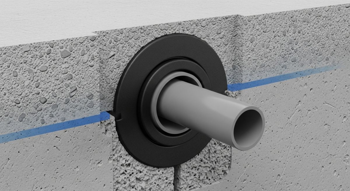
What is a Puddle Flange? Types, Applications, and Key Advantages
In my 20+ years of piping engineering, I have seen countless basements, water tanks, and subterranean vaults compromised not by pipe failures, but by water bypassing the pipe entirely. When you pour concrete around a smooth plastic or metallic pipe, a microscopic gap inevitably forms due to concrete shrinkage during curing. This gap becomes a path of least resistance for pressurized groundwater. That is where the puddle flange becomes your primary line of defense.
Whether you are dealing with high-density polyethylene (HDPE), PVC, ductile iron, or stainless steel piping, installing a dedicated waterstop collar is a non-negotiable requirement for structural integrity. In this guide, I will break down the engineering mechanics, material selections, and installation practices that make these components successful in the field.
Key Engineering Takeaways
- Shrinkage Mitigation: Concrete shrinks by approximately 0.03% to 0.06% during curing, creating a micro-annulus around smooth pipes.
- Path Extension: A puddle flange increases the water travel path by up to 50%, reducing the hydraulic gradient below critical leakage thresholds.
- Standard Compliance: Essential for meeting water-tightness criteria specified in BS EN 1992-3.
How Does a Puddle Flange Prevent Water Ingress?
To understand why a puddle flange is necessary, we must look at the physics of concrete curing. As concrete hydrates and dries, it undergoes volumetric contraction. Because the thermal expansion and contraction coefficients of plastic or metal pipes differ significantly from concrete, a microscopic separation gap forms at the interface.
Under hydrostatic pressure, water acts as a fluid seeking the path of least resistance. Without a barrier, water easily migrates along the smooth outer wall of the pipe. By introducing a perpendicular flange, we force the water to travel outward, around the flange, and back inward. This is known as creating a “tortuous path.”
The Hydraulic Gradient Calculation
The rate of water seepage through a porous medium or micro-gap is governed by Darcy’s Law, where the hydraulic gradient (i) is defined as:
i = H / L
Where:
- H = Hydrostatic head pressure (meters of water)
- L = Path of water travel (meters)
If a concrete wall is 300 mm (0.3 m) thick, the path of travel without a flange is exactly 0.3 m. If we install a puddle flange with a radial projection height (h) of 50 mm (0.05 m), the new effective path length (Leff) is calculated as:
Leff = L + (2 * h) = 0.3 + (2 * 0.05) = 0.4 meters
By increasing the path length from 0.3 m to 0.4 m, we increase the flow resistance by 33.3%, which drastically reduces the hydraulic gradient and prevents water from piping through the interface.
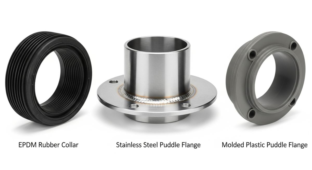
Primary Types of Puddle Flanges
Depending on the pipe material and project specifications, several types of puddle flanges are utilized in modern construction:
- Molded EPDM/NBR Rubber Collars: These are flexible, stretchable rings secured to the pipe using stainless steel band clamps. They are highly versatile and accommodate thermal expansion and minor structural settlement.
- Fabricated Metallic Flanges: Typically made of carbon steel or stainless steel (Grade 304 or 316), these are welded directly to metallic carrier pipes before the concrete pour. They offer maximum structural strength and are ideal for high-pressure applications.
- Monolithic Plastic Flanges: Often manufactured from PVC, PP, or HDPE, these are solvent-welded or butt-fused directly to plastic piping systems, ensuring a seamless, leak-proof bond.
In my field audits, I occasionally catch contractors attempting to weld scrap metal plates or wrap waterstop tape around pipes as a substitute for a certified puddle flange. These makeshift solutions lack the verified pressure ratings and chemical resistance required by BS 8007, often leading to costly structural remediation later.
Selecting the Right Puddle Flange Material
Selecting the wrong material can lead to galvanic corrosion, chemical degradation, or mechanical failure under load. The table below outlines the engineering parameters for the most common puddle flange materials used in industrial and civil applications.
| Material Type | Applicable Pipe Materials | Max Pressure Rating | Chemical Resistance | Key Standard |
|---|---|---|---|---|
| EPDM Rubber | PVC, HDPE, DI, Steel | Up to 10 Bar (145 PSI) | Excellent for water, dilute acids | ISO 48 (Hardness) |
| Stainless Steel 316L | Stainless Steel, Carbon Steel | Unlimited (Matches Pipe) | Outstanding (Corrosive/Wastewater) | ASTM A240 |
| Carbon Steel (Galvanized) | Ductile Iron, Carbon Steel | Unlimited (Matches Pipe) | Moderate (Requires coating) | ASTM A36 / EN 10025 |
| HDPE / PP | HDPE, PP (Fused) | Up to 16 Bar (232 PSI) | High chemical resistance | EN 12201 |
Technical Mapping & Specifications Matrix
To assist design engineers in specifying these components within piping layouts and structural drawings, the following matrix maps key technical entities and physical parameters.
| Technical Entity | Acronym | Physical Parameter / Value | Standard Reference |
|---|---|---|---|
| Concrete Drying Shrinkage | CDS | 0.03% to 0.06% volumetric reduction | ASTM C157 |
| Rubber Hardness (EPDM) | IRHD | 50 to 60 Shore A | ISO 48 |
| Hydrostatic Head Resistance | HHR | Up to 80 meters of water head | BS EN 1992-3 |
| Minimum Flange Projection | MFP | 50 mm radial height from pipe OD | Standard Civil Practice |
Site Installation Checklist for Puddle Flanges
In my years of supervising field installations, I have found that even the highest quality puddle flange will fail if the concrete surrounding it is poorly consolidated. Voids or honeycombing near the flange create direct bypass channels for water. Use this checklist on-site to ensure zero-leak performance.
Pre-Pour Verification Checklist
-
Surface Preparation: Ensure the outer surface of the carrier pipe is completely clean, free of grease, mud, rust, or loose scale where the flange will sit.
-
Positioning: Place the puddle flange in the exact center of the concrete wall or slab thickness to maximize the concrete cover on both sides.
-
Clamp Tensioning (for EPDM): Tighten the stainless steel band clamps evenly using a calibrated torque wrench to prevent localized deformation of plastic pipes.
-
Perpendicular Alignment: Verify that the flange is oriented at exactly 90 degrees to the pipe axis to prevent uneven stress distribution during concrete compaction.
-
Rebar Clearance: Maintain a minimum clearance of 50 mm between the puddle flange edge and the nearest reinforcement steel to prevent aggregate trapping.
-
Compaction Protocol: Ensure mechanical vibrators are used carefully around the pipe penetration to eliminate air pockets without directly striking the puddle flange.
Field Case Study: Real-World Application
The Problem: Severe Bypass Leakage in a Water Treatment Tank
During the commissioning of a municipal wastewater treatment plant, a 400 mm ductile iron inlet pipe passing through a 450 mm thick concrete wall began leaking heavily. The contractor had omitted the puddle flanges, relying solely on standard concrete pouring around the pipe. Under a hydrostatic head of 6 meters, water bypassed the pipe-concrete interface at a rate of 12 liters per minute, threatening to flood the adjacent dry pump room.
The Outcome: Retrofit and Complete Seal
I was called in to design a remediation plan. We excavated the exterior soil, core-drilled a concentric 600 mm pocket around the existing pipe, and installed a heavy-duty, split-type EPDM puddle flange collar secured with dual 316 stainless steel bands. The pocket was then packed with non-shrink, high-strength micro-concrete. Upon refilling the tank, the leak was completely arrested, demonstrating the critical role of the mechanical waterstop barrier.
This case highlights a vital lesson: attempting to save a small amount on component costs during initial construction almost always results in exponentially higher remediation costs later. Always insist on specifying and verifying puddle flanges during the design phase.
Frequently Asked Engineering Questions
1. Can a puddle flange be used on any pipe material?
2. What is the minimum concrete wall thickness required for installation?
3. How do puddle flanges compare to hydrophilic waterstops?
4. Are puddle flanges suitable for high-temperature pipelines?
5. Do puddle flanges provide structural support to the pipe?
6. What standards govern the design of these components?
===

Complete Course on
Piping Engineering
Check Now
Key Features
- 125+ Hours Content
- 500+ Recorded Lectures
- 20+ Years Exp.
- Lifetime Access
Coverage
- Codes & Standards
- Layouts & Design
- Material Eng.
- Stress Analysis