Guide to Types of Pumps and Their Working Principles
Over my 20 years in piping engineering, I have commissioned hundreds of pumps across petrochemical plants, water treatment facilities, and offshore platforms. I have seen how a minor misunderstanding of pump hydraulics can lead to catastrophic seal failures, destroyed impellers, and millions of dollars in unplanned downtime. In this guide, I will share my field-tested insights into the various pump designs, their operational mechanics, and how to select the right machine for your piping system.
Key Engineering Takeaways
- Understand the fundamental hydraulic differences between kinetic and positive displacement designs.
- Learn how to calculate Net Positive Suction Head (NPSH) to prevent destructive cavitation.
- Identify key industry standards like API 610 and ASME B73.1 for robust system design.
Analyzing Types of Pumps and Their Working
To design an efficient piping system, we must first categorize these machines. The broad classification splits pumps into two main families: Kinetic (primarily Centrifugal) and Positive Displacement (PD). Each family operates on distinct physical principles and serves specific process envelopes.
1. Centrifugal Pumps (Kinetic Energy Transfer)
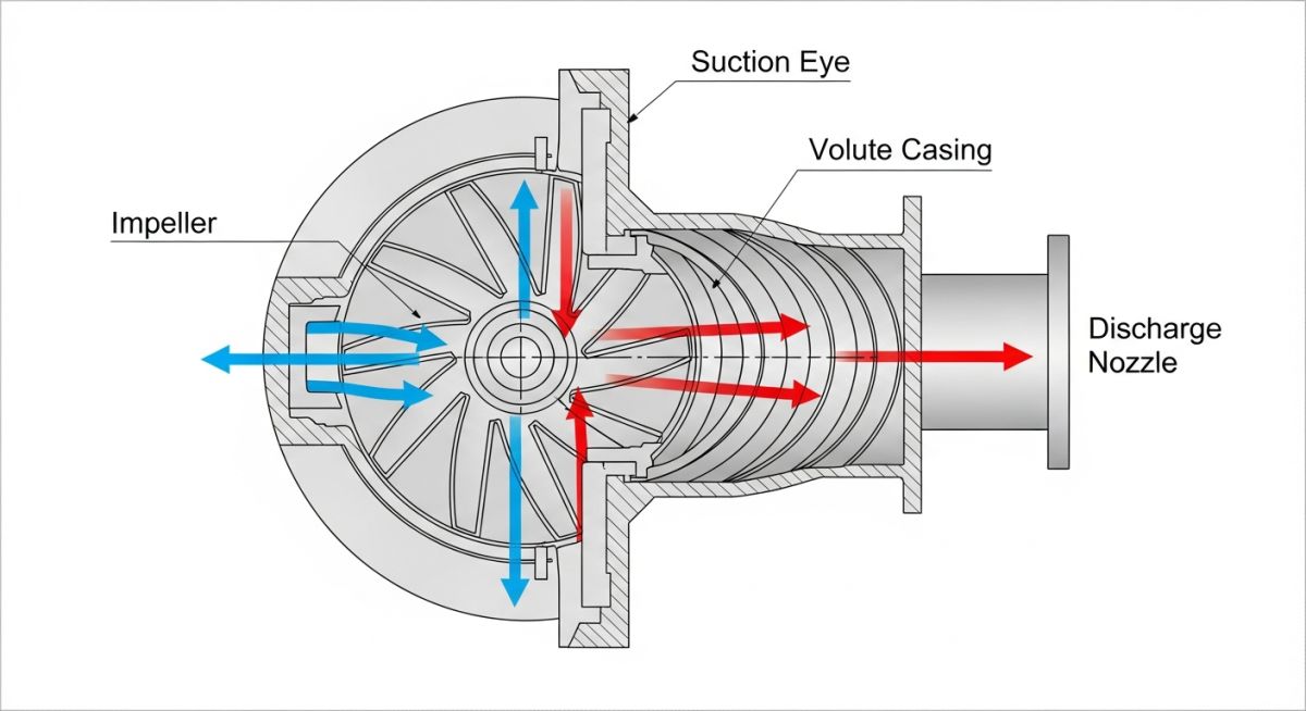
Centrifugal pumps are the workhorses of the process industry. They operate by transferring rotational kinetic energy from an impeller to the fluid. As the impeller rotates, it draws fluid into its eye and flings it outward radially via centrifugal force.
The fluid gains high velocity during this outward movement. This velocity energy is then converted into pressure energy within the expanding area of the volute casing or diffuser. This conversion is governed by Bernoulli’s principle, which dictates that as fluid velocity decreases, static pressure increases.
2. Positive Displacement Pumps (Constant Volume Transfer)
Unlike centrifugal pumps, positive displacement pumps do not rely on velocity. Instead, they physically trap a fixed volume of fluid at the suction side and force it out through the discharge nozzle. This mechanical action ensures a nearly constant flow rate regardless of the system’s discharge pressure.
PD pumps are divided into two primary sub-categories:
- Reciprocating Pumps: These use a piston, plunger, or flexible diaphragm moving back and forth. During the suction stroke, the cavity expands, drawing fluid in. During the discharge stroke, the cavity contracts, forcing fluid out through check valves. These are ideal for high-pressure, low-flow applications.
- Rotary Pumps: These utilize rotating elements like gears, screws, lobes, or vanes to move fluid. As these elements mesh and unmesh, they create low-pressure zones at the inlet and high-pressure zones at the outlet. They excel at handling highly viscous fluids like heavy oils and polymers.
Core Hydraulic Calculations
When I design a pumping system, I always perform three fundamental calculations to ensure long-term reliability:
A. Net Positive Suction Head Available (NPSHa):
NPSHa = (P_suction – P_vapor) / (density * gravity) + h_static – h_friction
Where:
P_suction = Absolute pressure at the suction source (Pascals)
P_vapor = Vapor pressure of the fluid at operating temperature (Pascals)
density = Fluid density (kg/m³)
gravity = Acceleration due to gravity (9.81 m/s²)
h_static = Static height of fluid above pump centerline (meters)
h_friction = Friction losses in the suction piping (meters)
B. Specific Speed (Ns):
Ns = (N * Q^0.5) / (H^0.75)
Where:
N = Rotational speed (RPM)
Q = Flow rate at Best Efficiency Point (m³/s)
H = Total Dynamic Head per stage (meters)
Mastering Types of Pumps and Their Working
To simplify the selection process, I have compiled a comprehensive performance comparison table. This table highlights the operating envelopes, advantages, and limitations of the most common pump types used in modern industrial plants.
| Pump Type | Flow Range | Pressure Range | Max Viscosity | Primary Advantage |
|---|---|---|---|---|
| Centrifugal (API 610) | 10 to 20,000 m³/h | Up to 150 bar | 150 cSt | Smooth, non-pulsating flow; low maintenance |
| Reciprocating Plunger | 1 to 500 m³/h | Up to 1,500 bar | 100 cSt | Extremely high pressure capability |
| Rotary Screw | 5 to 1,200 m³/h | Up to 120 bar | 1,000,000 cSt | Handles highly viscous fluids with low shear |
| Diaphragm (Air-Operated) | 0.5 to 60 m³/h | Up to 8 bar | 10,000 cSt | Excellent self-priming; runs dry without damage |
Technical Mapping & Specifications Matrix
The following matrix maps core technical entities, structural acronyms, physical parameters, and their governing international standards.
| Entity / Acronym | Physical Parameter | Governing Standard | Application Scope |
|---|---|---|---|
| OH2 (Overhung Single Stage) | Radial split, centerline mounted | API 610 | Heavy-duty refinery process services |
| BB3 (Between Bearings) | Axially split, multistage | API 610 | High-pressure water injection, crude pipelines |
| AODD (Diaphragm Pump) | Pneumatic displacement volume | ASME B73.3 | Chemical transfer, sump emptying, slurry handling |
| VS4 (Vertical Sump) | Line-shaft suspended, single casing | API 610 | Drainage sumps, open drain vessels |
How to Verify Pump Installations Onsite?
Before you push the start button on any newly installed pump, you must perform a rigorous physical inspection. Skipping these steps can lead to immediate mechanical seal failure or shaft breakage. Use this field-tested checklist during your next pre-commissioning phase.
Onsite Pump Verification Checklist
-
Foundation and Grouting: Verify that the baseplate is fully grouted with non-shrink epoxy grout and that all anchor bolts are torqued to specification.
-
Shaft Alignment: Perform laser alignment between the pump and driver shafts. Ensure parallel and angular misalignments are within API 686 tolerances (typically less than 0.05 mm).
-
Piping Strain Check: Mount dial indicators on the pump nozzles. Loosen the flange bolts and verify that nozzle movement does not exceed 0.05 mm. If it does, the piping must be re-supported.
-
Mechanical Seal Auxiliary Systems: Verify that the seal flush piping (e.g., API Plan 11, 21, or 53) is clean, free of leaks, and that all orifice plates are installed in the correct flow direction.
-
Direction of Rotation: Uncouple the motor and perform a brief “solo run” to verify that the motor rotates in the direction indicated by the arrow on the pump casing.
Field Case Study: Real-World Application
The Problem: Chronic Cavitation in a Hydrocarbon Transfer Pump
At a refinery in East Asia, a heavy gas oil transfer pump (API 610 OH2 type) suffered from severe vibration, high-pitched noise resembling “pumping gravel,” and mechanical seal failures every three months. The field operators suspected a mechanical defect, but my review of the piping isometric drawings revealed a different story. The suction line was 6 inches in diameter, containing three 90-degree elbows and a globe valve, which created massive friction losses. The calculated NPSHa was only 3.2 meters, while the pump’s NPSHr was 3.0 meters—leaving a margin of just 0.2 meters, far below the industry-standard margin of 1.0 meter.
The Outcome: Piping Re-Engineering and Hydraulic Restoration
I led the engineering team to redesign the suction piping system. We replaced the 6-inch line with an 8-inch line to reduce fluid velocity and friction losses. We also replaced the restrictive globe valve with a full-port gate valve and simplified the routing to eliminate two 90-degree elbows. These modifications reduced suction friction losses from 1.2 meters to 0.3 meters, successfully raising the NPSHa to 4.1 meters. This provided a robust 1.1-meter margin over the NPSHr.
Following these piping modifications, the pump’s vibration levels dropped from 8.5 mm/s to a smooth 1.8 mm/s. The mechanical seals have now run for over three years without a single leak, saving the plant operator thousands of dollars in maintenance costs and preventing unscheduled production shutdowns.
Frequently Asked Engineering Questions
What is the difference between NPSHa and NPSHr?
Why do centrifugal pumps require priming before startup?
How does fluid viscosity affect centrifugal pump performance?
What is the purpose of a minimum flow bypass line?
When should I choose a positive displacement pump over a centrifugal pump?
What are the consequences of running a pump far to the right of its BEP?
===
Complete Course on
Piping Engineering
Check Now
Key Features
- 125+ Hours Content
- 500+ Recorded Lectures
- 20+ Years Exp.
- Lifetime Access
Coverage
- Codes & Standards
- Layouts & Design
- Material Eng.
- Stress Analysis