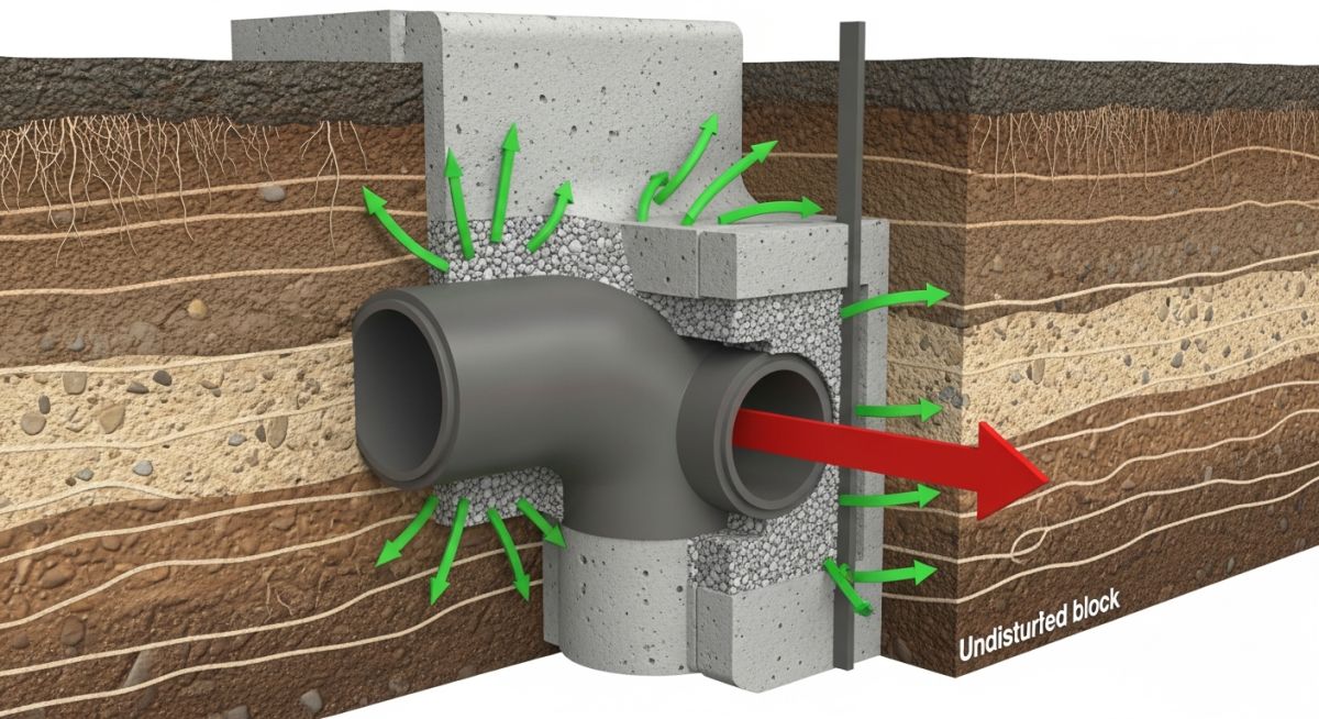
What is a Thrust Block and How Does It Work
In my 20 years of piping engineering, I have seen many pipeline failures that could have been easily avoided. One of the most common culprits is the failure to properly restrain directional changes. When fluid under pressure flows through a pipe, it exerts massive forces at elbows, tees, and dead ends. Without a reliable thrust block, these forces will literally pull the pipe joints apart, leading to catastrophic washouts. Let me take you through the exact engineering principles, design calculations, and field realities of these critical concrete structures.
Key Engineering Takeaways:
- Thrust blocks transfer hydraulic forces from the pipe directly to the surrounding undisturbed soil.
- They are primarily used for unrestrained joint systems like bell-and-spigot or mechanical joints.
- Proper soil bearing capacity assessment is the single most important factor in design.
- They differ fundamentally from anchor blocks, which restrict all thermal and structural movement.
How to Design a Concrete Thrust Block
[Thrust Block Design]: [The engineering design of a concrete thrust block requires calculating the resultant dynamic thrust force and sizing the bearing area against the soil’s allowable bearing capacity in compliance with AWWA M9 guidelines].
When designing a thrust block, we must first calculate the total thrust force generated by the internal pressure and fluid momentum. This force is a vector sum of the static pressure force and the dynamic momentum force. In most municipal and industrial water systems, the dynamic momentum force is negligible compared to the static pressure force, but we always calculate both to be safe.
The Governing Formula for Thrust Force at a Bend:
Where:
T = Hydrostatic thrust force (pounds or Newtons)
P = Internal design pressure (psi or Pascals), which must include water hammer allowance
A = Cross-sectional area of the pipe (square inches or square meters) based on the outside diameter
theta = Angle of the bend (degrees, e.g., 90, 45, 22.5)
For dead ends, tees, and reducers, the formula simplifies because the force acts in a single direction. For a dead end or tee branch, the thrust force is simply:
Once we have the thrust force, we must size the bearing area of the block that presses against the soil. This is where many field engineers make mistakes. The block must transfer the force to undisturbed soil. If the soil has been excavated and backfilled, its bearing capacity is severely compromised.
The Bearing Area Formula:
Where:
Ab = Required bearing area of the block against the soil (square feet or square meters)
FS = Safety factor (typically 1.5 for normal operating pressure, 2.0 for transient surge conditions)
Sb = Allowable soil bearing capacity (pounds per square foot or Pascals)
CRITICAL FIELD WARNING:
Never pour concrete directly over pipe joints, bolts, or fittings. If you encase the joint, future maintenance becomes impossible, and any slight settlement will concentrate stress directly on the pipe wall, causing a shear failure. Always wrap the pipe joint in plastic sheeting before pouring concrete.
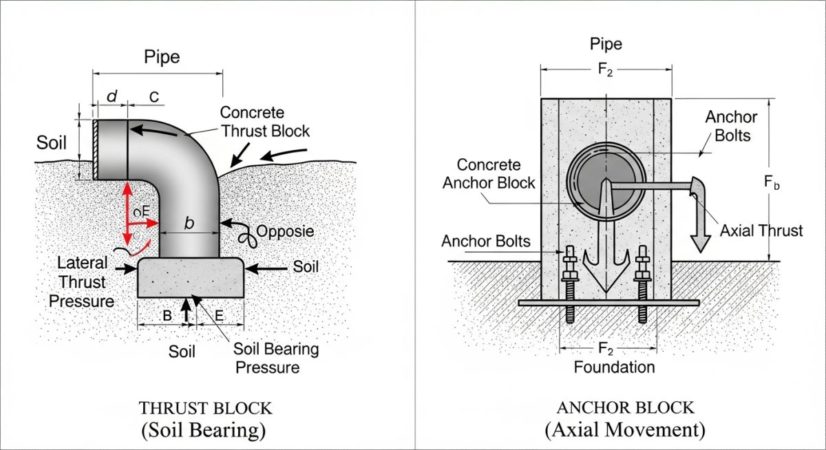
In my experience, soil conditions can vary wildly across a single pipeline trench. A design that works perfectly in stiff clay will fail miserably in soft sand. Always consult a geotechnical report or use conservative soil bearing values from codes like AWWA C600.
Sizing Parameters for a Thrust Block
[Thrust Block Sizing]: [Standard sizing parameters dictate the minimum concrete volume and bearing area required for various pipeline diameters and operating pressures under standard soil conditions].
The table below provides typical bearing areas and concrete volumes for a 90-degree bend operating at a design pressure of 150 psi (including water hammer) in standard sand/gravel soil with an allowable bearing capacity of 2,000 psf.
| Nominal Pipe Size (inches) | Thrust Force (lbs) | Required Bearing Area (sq ft) | Est. Concrete Volume (cu yd) | Min. Concrete Strength (psi) |
|---|---|---|---|---|
| 6 | 7,600 | 5.7 | 0.3 | 3,000 |
| 12 | 28,500 | 21.4 | 1.2 | 3,000 |
| 18 | 62,000 | 46.5 | 2.8 | 3,000 |
| 24 | 108,000 | 81.0 | 5.5 | 3,000 |
This matrix maps the core technical entities, structural acronyms, physical parameters, and hyperlinked standard references used in pipeline restraint design.
| Technical Entity | Acronym | Physical Parameter | Standard Reference |
|---|---|---|---|
| Hydrostatic Thrust Force | HTF | Pounds (lbs) / Kilonewtons (kN) | AWWA M9 |
| Allowable Soil Bearing Capacity | ASBC | Pounds per Square Foot (psf) | ASTM D1586 |
| Concrete Compressive Strength | f’c | Pounds per Square Inch (psi) | ACI 318 |
| Liquid Pipeline Systems | LPS | Operating Pressure (psi) | ASME B31.4 |
Site Inspection Checklist for Construction
[Thrust Block Construction]: [Field verification of concrete placement, soil compaction, and clearance from pipe joints ensures the structural integrity of the thrust block system prior to hydrostatic testing].
During my site audits, I often find that field crews rush the concrete pour without verifying the soil interface. If the concrete is poured against loose backfill or mud, the block will fail when the line is pressurized. Use this checklist on your next project to ensure compliance.
Field Verification Checkpoints:
-
Undisturbed Soil: Verify that the excavation face is cut into undisturbed, native soil. Any loose material must be hand-shoveled out. -
Polyethylene Barrier: Ensure a minimum 8-mil plastic sheet is wrapped around the pipe and fittings to prevent concrete from bonding to the pipe material. -
Joint Clearance: Visually inspect that all mechanical joint bolts, gaskets, and flanges are completely clear of concrete to allow for future maintenance. -
Concrete Mix Design: Confirm the delivery ticket matches the specified compressive strength (minimum 3,000 psi per ACI 318). -
Curing Time: Ensure the concrete cures for at least 5 days (or reaches 70% design strength) before initiating hydrostatic testing.
Field Case Study: Real-World Application
The Problem:
A 24-inch municipal water main elbow failed during a transient surge event (water hammer). The original contractor poured a small, unreinforced concrete block on loose, backfilled soil without calculating the actual thrust force. The block shifted 4 inches, pulling the mechanical joint apart and flooding a major roadway.
The Outcome:
I was called in to redesign the system. We calculated a peak surge pressure of 250 psi, resulting in a thrust force of over 78,000 lbs at the 90-degree elbow. We designed a reinforced concrete block with a bearing area of 52 square feet, resting against undisturbed stiff clay. The block was poured with a protective poly-wrap barrier. The system successfully passed a 300 psi hydrostatic test and has operated without issue for over five years.
My direct recommendation is to always perform a transient surge analysis for pipelines larger than 12 inches. Standard operating pressures do not tell the whole story; water hammer can easily double the design pressure, destroying under-designed thrust blocks.
Frequently Asked Engineering Questions
What is the fundamental difference between a thrust block and an anchor block?
When is a thrust block not required in a pipeline?
Can we use thrust blocks for vertical bends?
Why must we use a plastic wrap between the pipe and the concrete?
How long must concrete cure before hydrotesting a pipeline?
What happens if the soil bearing capacity is lower than expected?
Complete Course on
Piping Engineering
Check Now
Key Features
- 125+ Hours Content
- 500+ Recorded Lectures
- 20+ Years Exp.
- Lifetime Access
Coverage
- Codes & Standards
- Layouts & Design
- Material Eng.
- Stress Analysis
