What is a Thermal Relief Valve? TRV vs PRV Explained
In my 20 years of piping engineering, I have seen minor design oversights lead to catastrophic field failures. One of the most common oversights is neglecting the massive pressure spikes caused by thermal expansion in blocked-in liquid lines. When a liquid-filled pipeline is isolated by closed valves and exposed to solar radiation or steam tracing, the liquid tries to expand. Because liquids are virtually incompressible, even a tiny temperature rise can cause pressures to exceed the pipe’s yield strength within minutes. This is where a thermal relief valve becomes your system’s primary safety shield.
Throughout my career, I have guided young engineers through the nuances of overpressure protection. While many use the terms TRV and PRV interchangeably, they serve distinct roles, have different sizing criteria, and operate under different mechanical limits. Understanding these differences is not just an academic exercise; it is a fundamental requirement for plant safety, environmental compliance, and asset integrity.
Key Engineering Takeaways
- TRVs protect isolated liquid-filled systems from thermal expansion, whereas PRVs handle large-scale process overpressure events.
- A temperature increase of just 1 degree Fahrenheit in a blocked-in liquid line can raise internal pressure by 50 to 100 psi.
- TRVs typically utilize small orifices (such as “D” or “E” sizes) because the required relief volume for thermal expansion is extremely small.
Why Every Piping System Needs a Thermal Relief Valve
To understand why a thermal relief valve is necessary, we must look at the physics of trapped liquids. When a liquid is locked inside a pipe run between two closed isolation valves, it forms a closed thermodynamic system. If heat is added to this system—whether from ambient air, direct sunlight, or adjacent steam lines—the liquid attempts to expand. The coefficient of volumetric expansion governs this behavior.
Because the steel pipe walls offer high rigidity, the expanding liquid exerts tremendous force outward. The resulting pressure rise can be calculated using the physical properties of the fluid and the piping material. In my field experience, a standard carbon steel pipe filled with water will experience a pressure increase of approximately 75 psi for every single degree Fahrenheit rise in temperature. For hydrocarbons, this spike can be even more severe.
The API 521 Sizing Formula
To size a thermal relief valve for liquid expansion, we refer to the standard sizing equations provided in API Standard 521. The required volumetric relief flow rate is calculated as follows:
Where:
gpm = Volumetric flow rate (gallons per minute)
B = Coefficient of volumetric expansion of the trapped liquid (1/deg F)
q = Total heat transfer rate to the trapped liquid (Btu/hr)
G = Specific gravity of the liquid
c = Specific heat capacity of the liquid (Btu/lb-deg F)
Because the heat transfer rate (q) from solar radiation or ambient air is relatively small compared to process heat exchangers, the resulting volumetric flow rate (gpm) is almost always very low—often less than 1 gpm. Consequently, a TRV does not need a large flow area. This is why standard thermal relief valves are compact, typically featuring a 3/4-inch or 1-inch inlet and a “D” or “E” orifice size as defined by ASME Section VIII.
In my early days as a field engineer, I witnessed a piping manifold rupture because an operator closed both isolation valves on a diesel line during a hot summer afternoon without opening the bleed valve. The pressure built up so rapidly that a 150-pound class flange gasket blew out, spraying diesel across the unit. Always ensure that any piping section that can be isolated has a dedicated thermal relief valve or an active, locked-open bleed path.
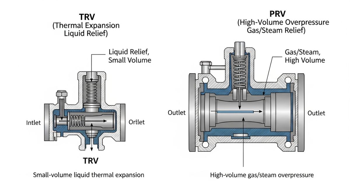
While both TRVs and PRVs are overpressure protection devices, their design philosophies diverge significantly. A PRV is designed to handle massive, rapid volume surges during process upsets, such as control valve failures, utility failures, or external pool fires. A TRV, on the other hand, is a highly sensitive, small-capacity valve designed specifically to bleed off the tiny volumes of liquid generated by thermal expansion.
Key Differences Between TRV and PRV Systems
To help my project teams select the correct valve, I developed a comparative framework. The table below outlines the critical engineering differences between these two essential safety components.
| Technical Parameter | Thermal Relief Valve (TRV) | Pressure Relief Valve (PRV) |
|---|---|---|
| Primary Function | Protects isolated piping/vessels from thermal expansion. | Protects systems from process upsets, fires, or equipment failures. |
| Fluid State | Almost exclusively liquid service. | Gas, vapor, steam, or multi-phase mixtures. |
| Typical Orifice Size | Small (Orifice D or E, 0.11 to 0.196 sq. in.). | Medium to Large (Orifice F through T, up to 26 sq. in.). |
| Inlet/Outlet Sizes | Typically 3/4″ x 1″ or 1″ x 1-1/2″. | Ranges from 1″ x 2″ up to 8″ x 10″ or larger. |
| Relief Flow Capacity | Very low (typically 1 to 10 gpm). | High to extremely high (thousands of gpm or lb/hr). |
| Code Compliance | API 521, ASME Sec VIII. | API 520, API 526, ASME Sec VIII. |
This matrix maps the core technical entities, standard codes, and physical parameters that govern the design and installation of thermal relief systems.
| Entity / Acronym | Technical Definition | Physical Parameter / Value | Standard Reference |
|---|---|---|---|
| TRV | Thermal Relief Valve | Set pressure matches piping design limit. | API 521 Section 5.14 |
| Orifice D | Standard small-bore relief area. | 0.110 square inches (71 square mm). | API 526 |
| Orifice E | Standard medium-bore relief area. | 0.196 square inches (126 square mm). | API 526 |
| Overpressure Limit | Maximum allowable pressure during relief. | 10% or 21% above design pressure. | ASME Sec VIII Div 1 |
Field Inspection Checklist for Thermal Relief Valve Setup
Before any process plant is commissioned, every safety valve must undergo rigorous field verification. Based on my years of managing pre-commissioning teams, I compiled this checklist to prevent common installation errors that could compromise the valve’s operation.
Pre-Commissioning Verification Steps
-
Verify Set Pressure: Ensure the set pressure stamped on the TRV nameplate matches the piping isometric drawing and does not exceed the design pressure of the weakest component in the isolated loop.
-
Confirm Flow Direction: Check the arrow cast on the valve body. Installing a TRV backward is a critical error that completely blocks relief flow.
-
Inspect Isolation Valves: If isolation valves are installed upstream or downstream of the TRV for maintenance, they must be locked in the open position (Car-Sealed Open – CSO) during normal operation.
-
Check Discharge Piping: Ensure the discharge line slopes downward toward the recovery header or slop tank to prevent liquid pooling, which can create backpressure on the valve.
-
Verify Bonnet Venting: For bellows-type TRVs, ensure the bonnet vent is open to the atmosphere and not plugged, allowing the bellows to flex freely.
-
Confirm Material Compatibility: Verify that the valve body and trim materials match the piping specification, especially in corrosive or sour services (NACE MR0175 compliance).
Field Case Study: Real-World Application
The Problem: Flange Leakage in a Diesel Transfer Line
During a scheduled maintenance turnaround at a coastal storage terminal, a 10-inch diesel transfer line was isolated. The line was completely filled with diesel at 65 degrees Fahrenheit. Over the course of the afternoon, intense solar radiation heated the stagnant diesel inside the pipe, raising its temperature to 115 degrees Fahrenheit.
Because there was no thermal relief valve installed on this isolated run, the pressure spiked rapidly, exceeding 1,200 psig. This pressure far exceeded the rating of the Class 150 flanges (285 psig at ambient temperature). The result was a sudden, violent gasket blowout at a flange joint, releasing approximately 50 barrels of diesel into the containment dike and creating a major environmental cleanup challenge.
The Outcome: Retrofitting a Dedicated TRV
My team was called in to perform a root cause analysis and design a permanent solution. We calculated the volumetric expansion rate of the diesel using the API 521 formula. The required relief rate was determined to be only 0.45 gpm.
We retrofitted a 3/4-inch x 1-inch thermal relief valve with a “D” orifice, set to relieve at 250 psig. The discharge was routed safely to the terminal’s slop system. During the next maintenance shutdown under similar ambient conditions, the TRV functioned perfectly, cycling briefly to bleed off less than a gallon of diesel, maintaining the system pressure well within safe limits, and preventing any further environmental or mechanical incidents.
This case study highlights a fundamental truth in piping design: never underestimate the power of thermal expansion. A simple, cost-effective TRV installation can save millions of dollars in environmental cleanup costs, equipment damage, and lost production time.
Common Thermal Relief Valve Queries Answered
What is the typical orifice size for a thermal relief valve?
Can a thermal relief valve be used for gas or vapor service?
How do you determine the set pressure of a TRV?
Is a bypass valve required around a thermal relief valve?
What is the difference between a TRV and a thermal expansion joint?
How often should a thermal relief valve be calibrated?
Complete Course on
Piping Engineering
Check Now
Key Features
- 125+ Hours Content
- 500+ Recorded Lectures
- 20+ Years Exp.
- Lifetime Access
Coverage
- Codes & Standards
- Layouts & Design
- Material Eng.
- Stress Analysis