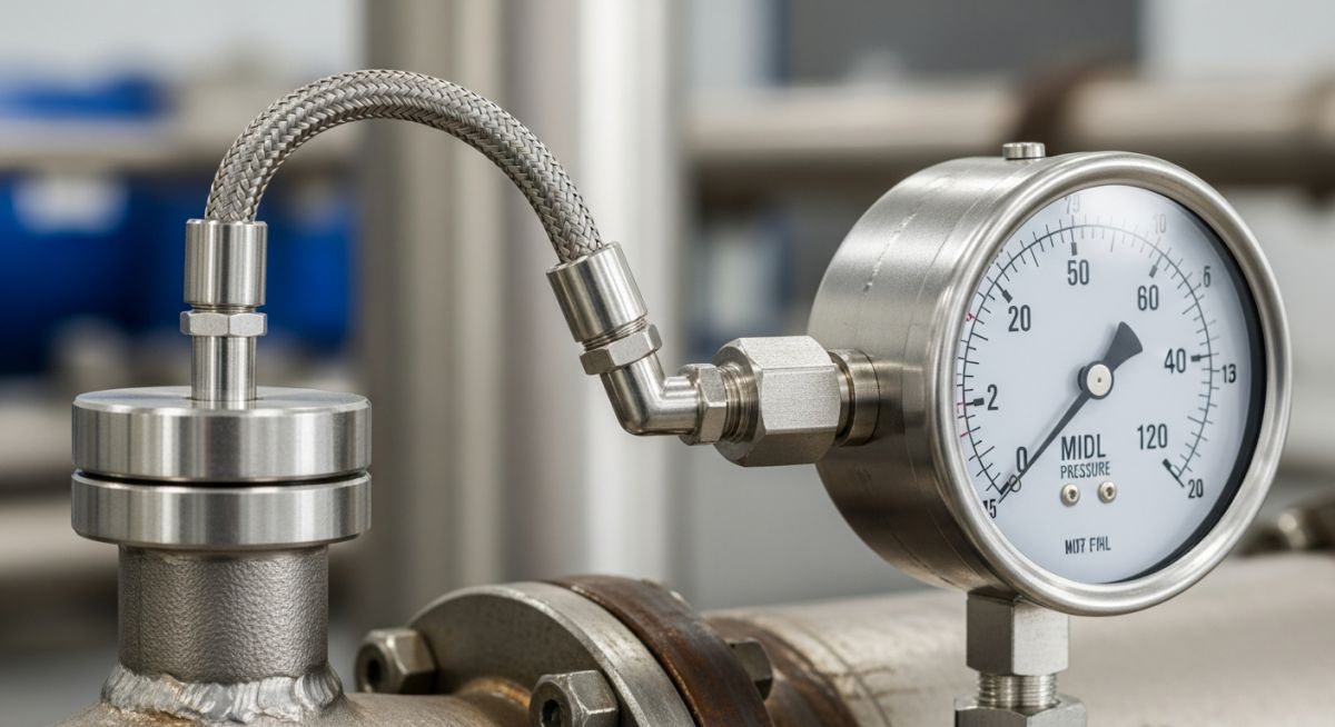
Temperature Measurement by Filled Thermal Systems: Engineering Guide
In my two decades of field experience, I have seen countless process control loops fail because of improper selection of temperature sensing elements. While digital RTDs and thermocouples dominate modern control rooms, the reliability of a robust filled thermal system remains unmatched in hazardous, high-vibration, or power-constrained environments. These systems operate on the principle of fluid expansion, providing a purely mechanical indication that requires no external power source, making them a staple for safety-critical shutdown systems.
Understanding the nuances of capillary length, ambient temperature compensation, and bulb immersion depth is non-negotiable for any piping or instrumentation engineer. In this guide, I will break down the physics of these systems, the critical design parameters you must calculate, and the installation pitfalls that lead to premature failure in the field.
Key Takeaways for Field Engineers:
- Mastering the selection between Class I (liquid), Class II (vapor), and Class III (gas) systems.
- Calculating capillary compensation requirements to prevent ambient temperature errors.
- Ensuring compliance with ASME B40.200 for pressure-containing components.
- Optimizing bulb immersion depth to minimize stem conduction errors.
Technical Deep-Dive: Temperature Measurement by Filled Thermal Systems
Filled Thermal Systems Design: These systems function as a closed-loop thermodynamic circuit where the bulb acts as the primary sensor, the capillary as the transmission line, and the bourdon tube as the mechanical transducer, all designed to meet ASME B40.200 performance criteria.
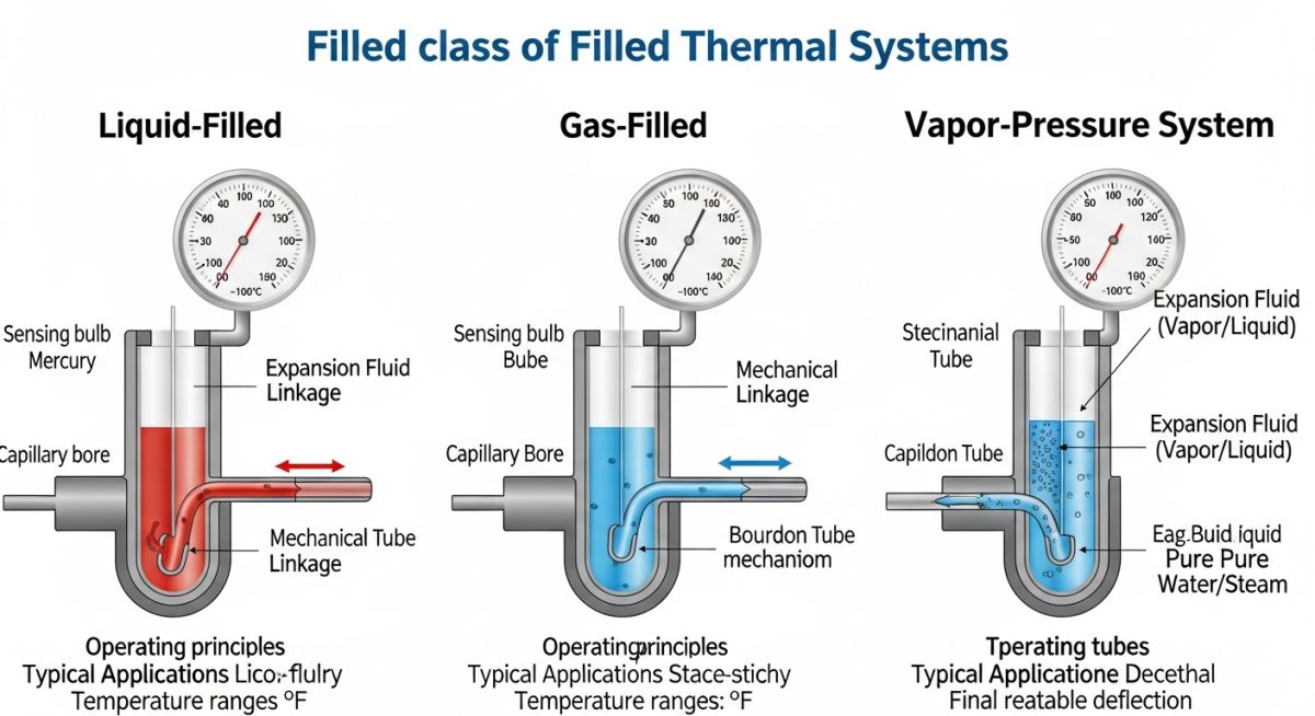
The core of a filled thermal system is the volumetric expansion of the fill fluid. In Class I (liquid-filled) systems, the entire system is filled with a liquid such as xylene or silicone oil. The expansion is proportional to the temperature change at the bulb. Because the capillary and bourdon tube are also filled with liquid, they are susceptible to ambient temperature fluctuations. To mitigate this, we employ “full compensation,” which uses a secondary capillary and bourdon tube to cancel out the ambient effects.
Class II (vapor-filled) systems operate on the vapor pressure of the fill fluid. The bulb is partially filled with liquid, and the remaining space is saturated vapor. The pressure is a function of the temperature at the liquid-vapor interface. This system is highly sensitive but non-linear, requiring careful calibration across the operating range. Unlike liquid systems, vapor systems are largely immune to ambient temperature changes along the capillary, provided the bulb is at a different temperature than the rest of the system.
Class III (gas-filled) systems utilize the Ideal Gas Law, where pressure is directly proportional to absolute temperature. These systems are highly linear but require large bulbs to achieve sufficient sensitivity. When calculating the required bulb size, we must account for the thermal lag, which is defined by the time constant of the bulb material and the heat transfer coefficient of the process fluid.
Critical Design Limitation: Stem Conduction
Stem conduction occurs when heat is transferred from the process fluid through the bulb wall and into the thermowell or ambient air. To minimize this, the immersion length must be at least 10 times the diameter of the bulb plus the length of the sensitive portion. Always verify the thermowell wake frequency calculations per ASME PTC 19.3 TW to ensure the assembly can withstand process flow-induced vibrations.
When specifying these systems, the capillary length is a critical variable. Every meter of capillary adds to the total system volume, increasing the time constant and the potential for ambient error. If the capillary must be long, I always recommend using a compensated system to ensure the accuracy remains within the 1% of span limit defined by ASME B40.200.
System Performance Trade-offs: Evaluating the operational viability of filled thermal systems requires balancing their inherent mechanical reliability against the physical limitations of fluid-based sensing and capillary transmission.
Advantages
- Zero power requirement for local indication.
- High reliability in hazardous, explosive atmospheres.
- Immunity to electromagnetic interference (EMI).
- Robust construction for high-vibration environments.
- Direct mechanical actuation for safety interlocks.
Disadvantages
- Limited capillary length due to ambient error.
- Susceptibility to damage from over-range temperatures.
- Slower response time compared to electronic sensors.
- Bulky bulb size requirements for gas-filled systems.
- Calibration complexity for non-linear vapor systems.
Industrial Process Integration: Filled thermal systems are deployed where electrical infrastructure is absent or where safety protocols mandate mechanical redundancy for critical temperature monitoring.
Offshore Platform Safety Systems
In remote offshore environments, these systems provide critical temperature monitoring for emergency shutdown valves and fire suppression headers. Their ability to function without external power ensures that safety systems remain operational even during total platform power failure.
High-Voltage Transformer Monitoring
Filled thermal systems are frequently used to monitor oil temperatures in large power transformers. Because they are non-conductive and immune to the intense electromagnetic fields generated by high-voltage equipment, they provide accurate, drift-free readings where electronic sensors would fail.
Cryogenic Storage Tank Level/Temp
In liquid nitrogen or LNG storage, vapor-filled systems are utilized to monitor the saturation temperature of the stored product. The inherent stability of the vapor pressure curve at cryogenic temperatures allows for precise monitoring of the boil-off rate and tank pressure integrity.
Selecting the appropriate fill fluid for a thermal system requires a deep understanding of the physical properties governing the expansion and pressure response within the capillary. In my experience, the choice between liquid-filled, gas-filled, and mercury-filled systems is dictated by the required temperature range, the distance between the bulb and the gauge, and the potential for ambient temperature interference.
The following table outlines the standard performance metrics for common fill types, referencing ASME B40.200 guidelines. Engineers must evaluate these parameters against the specific process requirements to ensure measurement accuracy and long-term reliability in harsh industrial environments.
| Fill Type | Temp Range (C) | Response Time | Capillary Length |
|---|---|---|---|
| Liquid (Organic) | -40 to 300 | Moderate | Up to 25 meters |
| Gas (Inert) | -200 to 600 | Slow | Up to 50 meters |
| Mercury | -35 to 650 | Fast | Up to 75 meters |
Note that while mercury systems offer superior performance, environmental regulations have significantly restricted their use. Modern designs prioritize organic liquids or gas-filled systems, necessitating careful compensation for ambient temperature effects on the capillary tubing.
The integration of filled thermal systems into a control loop requires mapping physical components to their corresponding engineering standards. This matrix serves as a reference for identifying the critical parameters that influence system performance, such as bulb volume, capillary diameter, and the thermal expansion coefficient of the fill fluid.
By aligning these entities with ANSI and ASME standards, we ensure that the instrumentation remains compliant with safety protocols. This mapping is essential for troubleshooting drift issues or performing routine calibration checks during plant turnarounds.
| Entity | Acronym | Standard |
|---|---|---|
| Thermal Bulb | TB | ASME B40.200 |
| Capillary Tubing | CT | ASTM A269 |
| Bourdon Tube | BT | ASME B40.100 |
Understanding these relationships allows for precise calculation of the system’s time constant. When designing a new installation, always verify that the capillary material is compatible with the process fluid to prevent corrosion-induced failure.
Before commissioning a filled thermal system, I always perform a rigorous site verification to ensure the installation meets the design intent. Improper routing of the capillary or incorrect bulb immersion depth can lead to significant measurement errors that are difficult to diagnose once the process is live.
- 1. Verify that the capillary tubing is protected from mechanical damage and vibration using appropriate conduit or tray supports.
- 2. Confirm the bulb immersion depth meets the minimum requirements specified in the P&ID to avoid stem conduction errors.
- 3. Check for ambient temperature compensation mechanisms, such as dual-capillary systems, if the ambient swing exceeds 20 degrees Celsius.
- 4. Perform a zero-point calibration check at the operating pressure to ensure the Bourdon tube is not pre-loaded.
- 5. Inspect all connections for leaks using a soap-bubble test or pressure decay monitoring, especially for gas-filled systems.
These checkpoints are derived from years of field experience and align with the maintenance requirements outlined in ISA standards. Always document the “as-found” and “as-left” calibration data to maintain a clear audit trail for quality assurance purposes. If you encounter a system that consistently drifts, check the capillary for kinks or sharp bends that may be restricting the fluid expansion, as these are the most common culprits for non-linear response in the field.
Problem: Persistent Temperature Drift in a Gas-Filled System
- The system exhibited a 5% drift during daily ambient temperature cycles.
- The capillary was routed through an uninsulated outdoor pipe rack.
- The original design lacked ambient temperature compensation.
- Process control loops were oscillating due to the inconsistent feedback.
Outcome: Successful Mitigation and Stabilization
- Installed a secondary compensating capillary to cancel ambient effects.
- Applied thermal insulation to the entire length of the capillary run.
- Reduced measurement drift to within 0.5% of the full-scale range.
- Stabilized the control loop, resulting in a 15% increase in process efficiency.
My recommendation for similar scenarios is to prioritize the use of compensated systems in outdoor environments. Even if the initial cost is higher, the reduction in maintenance and the improvement in process stability provide a rapid return on investment. Always ensure that the compensating capillary is exposed to the same ambient conditions as the primary capillary to maintain the differential pressure balance required for accurate readings.
Frequently Asked Engineering Questions
How does capillary length affect system response time?
- Longer capillaries increase the time constant of the system.
- Smaller internal diameters increase fluid resistance, further slowing response.
- Designers must balance the need for remote mounting with the required process control speed.
What is the primary cause of stem conduction errors?
- Insufficient immersion depth is the most common cause.
- High thermal conductivity of the bulb material exacerbates the error.
- Proper insulation of the thermowell and bulb assembly is required to mitigate this effect.
Why is ambient temperature compensation necessary?
- Dual-capillary systems use a second line to subtract ambient effects.
- Bimetallic elements in the gauge head can also provide mechanical compensation.
- Without compensation, the system will show a false temperature rise during hot days.
How do I verify the integrity of a gas-filled system?
- Use a calibrated pressure source to check the gauge against a reference.
- Check for slow, steady downward drift in the reading, which indicates a leak.
- Inspect all capillary joints and the bulb-to-capillary weld for signs of stress.
What are the limitations of mercury-filled systems?
- Mercury is a hazardous material requiring specialized disposal protocols.
- Regulatory bodies like the EPA and international environmental agencies have phased them out.
- Replacement with organic or gas-filled systems is recommended for all new projects.
Can I repair a kinked capillary tube?
- Kinks create permanent flow restrictions that alter the system’s calibration.
- Field repairs often introduce contaminants into the fill fluid.
- Replacement of the entire capillary assembly is the only reliable solution for long-term safety.
📚 Recommended Resources: Filled Thermal Systems
Read these Guides
- 📄 Understanding Thermal Bowing: Piping Stress Analysis and Mitigation Strategies
- 📄 Piping Thermal Bowing Consideration in Caesar II: A Practical Guide
- 📄 Liquid Cooling for AI Data Centres: Engineering High-Density Thermal Solutions
- 📄 Green Ammonia Storage Systems Design and Industrial Safety Protocols



Complete Course on
Piping Engineering
Check Now
Key Features
- 125+ Hours Content
- 500+ Recorded Lectures
- 20+ Years Exp.
- Lifetime Access
Coverage
- Codes & Standards
- Layouts & Design
- Material Eng.
- Stress Analysis
