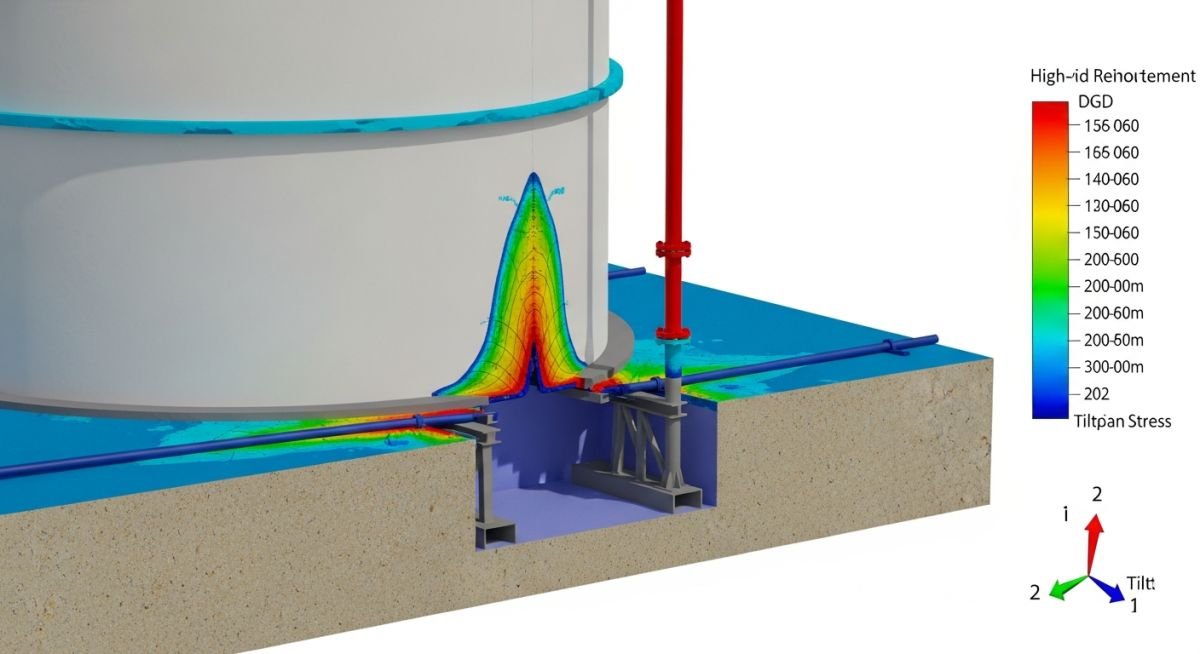
Storage Tank Settlement for Piping Stress Analysis
In my two decades of piping design, I have seen too many projects stall because the civil foundation team and the piping stress group worked in silos. When a massive storage tank settles—even by a few millimeters—it acts as a giant lever, imposing significant displacement-induced stresses on your piping nozzles. If your stress model doesn’t account for these differential movements, you are essentially waiting for a flange leak or a nozzle failure to occur during the first hydrotest or operational cycle.
This guide focuses on bridging that gap. We will look at how to translate geotechnical settlement reports into actionable displacement vectors for your stress software. We aren’t just talking about uniform settlement; we are talking about the tilt and differential settlement that actually breaks pipes.
Key Takeaways for Your Next Project:
- Translate geotechnical settlement predictions into X, Y, and Z displacement vectors.
- Apply API 650 Annex B criteria to define allowable tank movement.
- Integrate settlement cases into your CAESAR II or AutoPIPE load cases.
- Design flexible piping configurations to absorb foundation-induced nozzle rotations.
Engineering Analysis of Storage Tank Settlement
Storage Tank Settlement Analysis: The rigorous assessment of foundation-induced piping displacement, utilizing geotechnical data to verify that nozzle loads remain within the allowable limits defined by API 650 and equipment vendor specifications.
When I approach a project involving large-diameter storage tanks, the first thing I request is the geotechnical report. We need to distinguish between uniform settlement, which is rarely a problem for piping, and differential settlement or tilting, which is catastrophic. If a tank tilts, the nozzle moves not just vertically, but also rotates, creating a moment that the piping system must accommodate.
To calculate the impact, we define the displacement vector at the nozzle. If the tank settles by a value ‘S’ at the shell, the nozzle displacement is calculated as a function of the distance from the tank center. For a tilt angle ‘theta’, the vertical displacement ‘delta_v’ at a nozzle located at radius ‘R’ is ‘R multiplied by sin(theta)’. This displacement must be input into your stress software as a ‘displacement’ load case.
Critical Warning: The Nozzle Load Trap
Never assume that the tank nozzle can handle the same loads as a pump or compressor nozzle. API 650 provides guidance on shell flexibility, but it does not guarantee that the shell won’t buckle under excessive external piping moments. Always verify the local shell stress using WRC 107/297 or FEA if the calculated nozzle loads exceed the vendor’s standard allowable values.
In my experience, the most common error is failing to include the ‘operating’ versus ‘hydrotest’ settlement cases. During hydrotest, the tank is at its maximum weight, causing maximum settlement. Your piping must be designed to handle this displacement without exceeding the allowable stress range defined in ASME B31.3. I typically create a specific load case in my software: ‘Operating + Settlement’ and ‘Hydrotest + Settlement’.
If the settlement is predicted to be significant, I recommend installing a flexible piping loop or a bellows expansion joint near the nozzle. However, be cautious with bellows; they require proper guiding and anchoring to prevent squirm. A well-designed piping loop is almost always superior to a bellows in a high-settlement environment because it provides a passive, maintenance-free solution to accommodate the movement.
Settlement Mitigation Strategies: The evaluation of design choices for managing foundation movement, balancing the cost of flexible piping configurations against the long-term structural integrity of tank nozzles.
Advantages of Proactive Analysis
- Prevents premature flange leakage during initial hydrotest cycles.
- Reduces the risk of shell buckling at the nozzle reinforcement pad.
- Ensures compliance with API 650 structural integrity requirements.
- Extends the operational life of the tank-to-piping connection.
- Allows for optimized support placement to minimize stress concentrations.
Disadvantages & Design Challenges
- Increases initial piping material and installation costs.
- Requires precise geotechnical data which may be unavailable early.
- Complex stress models increase engineering man-hour requirements.
- Flexible loops occupy significant plot space in congested areas.
- Bellows expansion joints introduce potential single-point failure risks.
Industrial Settlement Management: The application of structural and piping flexibility principles to mitigate the risks associated with foundation displacement in large-scale storage facilities.
Crude Oil Tank Farms
In massive crude oil tank farms, the sheer weight of the product causes significant soil consolidation. We implement long-radius piping loops to absorb the vertical settlement, ensuring that the nozzle loads remain within the limits specified by API 650, even when the tank settles by several inches over its lifetime.
LNG Terminal Storage
LNG tanks operate at cryogenic temperatures, which introduces thermal contraction alongside foundation settlement. The piping design must account for the combined effect of thermal movement and soil settlement, often requiring specialized cryogenic-rated expansion joints and rigorous stress analysis to prevent brittle failure at the nozzle.
Water Treatment Facilities
Large water storage tanks are often built on softer soils, leading to higher predicted settlement rates. By utilizing flexible piping connections and ensuring that the first support is placed at an optimal distance from the tank, we decouple the piping system from the tank’s movement, preventing stress transfer to the pump house.
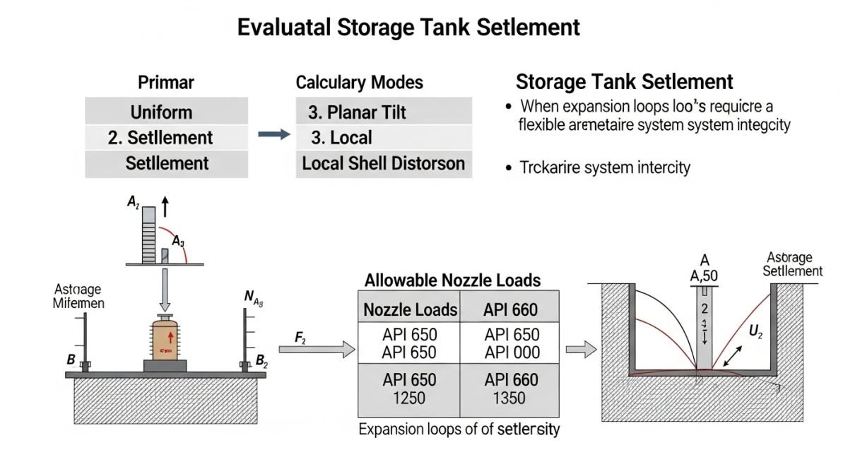
When evaluating storage tank settlement for piping stress analysis, engineers must distinguish between uniform settlement and differential settlement. Uniform settlement typically affects the entire tank foundation equally, resulting in a vertical displacement that is often manageable through standard piping flexibility loops. However, differential settlement—where the tank shell tilts or experiences localized sinking—creates severe bending moments and shear forces at the nozzle-to-pipe connection.
The following table outlines the typical allowable settlement thresholds derived from API 650 Appendix B and industry best practices for piping connectivity. These values serve as the primary input for your Caesar II or AutoPIPE models. Always verify these limits against the specific geotechnical report for your site, as soil bearing capacity and tank diameter significantly influence the allowable tilt before nozzle integrity is compromised.
| Settlement Type | Allowable Limit (Typical) | Piping Impact |
|---|---|---|
| Uniform Settlement | Up to 300 mm | Vertical nozzle displacement |
| Differential (Tilt) | L / 200 (Tank Diameter) | Nozzle rotation and bending |
| Edge Settlement | Per API 650 App B | Shell distortion at nozzle |
By integrating these values into your stress software, you can simulate the “worst-case” displacement scenario. Ensure that the piping system is modeled with sufficient flexibility to absorb these movements without exceeding the allowable nozzle loads defined by the tank manufacturer or ASME B31.3 stress intensification factors.
The complexity of managing storage tank settlement requires a structured approach to data mapping. We must correlate geotechnical soil parameters with mechanical piping constraints to ensure the structural integrity of the nozzle connection. This matrix provides a clear mapping of the entities involved in the calculation process, linking physical phenomena to the relevant engineering standards and software inputs.
Engineers should utilize this matrix to audit their design basis. Each entity represents a critical variable that, if ignored, leads to premature nozzle failure or piping fatigue. By standardizing these inputs, you ensure that your stress analysis reflects the actual field conditions observed during the tank’s operational lifecycle.
| Entity | Standard | Primary Function |
|---|---|---|
| Tank Shell Nozzle | API 650 | Interface point for piping |
| Settlement Vector | Geotech Report | Input for displacement analysis |
| Flexibility Analysis | ASME B31.3 | Stress limit verification |
This matrix is not exhaustive but covers the foundational elements required for a robust design. Always cross-reference these entities with the specific project specifications, as client-defined nozzle load limits often supersede general code requirements in high-risk environments.
Storage Tank Settlement verification is a multi-disciplinary task that bridges the gap between civil foundation design and mechanical piping stress analysis. Before finalizing your piping layout, you must validate that the predicted settlement values from the geotechnical team are accurately reflected in your stress model. This checklist ensures that no critical parameter is overlooked during the design phase.
-
Confirm the geotechnical report includes both total and differential settlement predictions for the tank foundation. -
Verify that the piping stress model includes the maximum predicted settlement as a displacement load case. -
Check that nozzle load limits are obtained from the tank manufacturer, not just generic API 650 tables. -
Ensure that expansion loops or flexible joints are positioned to accommodate the calculated shell rotation. -
Validate that the piping support system does not restrict the tank’s natural movement during settlement events.
In my experience, the most common failure point is the assumption that the tank will settle perfectly vertically. In reality, soil heterogeneity often causes a tilt, which introduces significant bending moments into the nozzle. Always perform a sensitivity analysis by applying the settlement vector in the most unfavorable direction relative to the piping run. If the resulting stresses exceed the allowable limits, you must introduce additional flexibility or coordinate with the civil team to improve foundation soil compaction.
The Problem: Excessive Nozzle Loading due to Unforeseen Differential Settlement
- A large-diameter crude oil tank experienced 150mm of differential settlement over a 12-month period.
- The rigid piping connection to the shell nozzle resulted in severe shell distortion and cracking at the weld.
- The original design failed to account for the soil’s non-uniform consolidation under the tank’s center.
- Piping stress analysis was performed only for thermal expansion, ignoring the settlement displacement vector.
The Outcome: Successful Mitigation and Structural Integrity Restoration
- Implemented a flexible piping configuration using multi-axis expansion joints to absorb the 150mm displacement.
- Re-calculated the nozzle loads using the actual settlement data, ensuring compliance with ASME B31.3.
- Installed a real-time monitoring system to track further settlement and provide early warning for piping stress.
- Reduced the stress at the nozzle-to-shell interface by 45% compared to the original rigid design.
My recommendation for similar projects is to always design for the “worst-case” settlement scenario from day one. Do not wait for the tank to settle before deciding on the piping flexibility. By incorporating a conservative settlement displacement into your initial stress analysis, you avoid costly field retrofits and ensure the long-term safety of your facility.
How does tank settlement affect nozzle loads?
- Vertical settlement creates axial and shear forces on the nozzle.
- Differential settlement induces rotation, leading to high bending moments.
- These forces must be checked against API 650 allowable loads.
What is the difference between uniform and differential settlement?
- Uniform settlement is usually handled by simple pipe flexibility.
- Differential settlement requires complex stress analysis and potential expansion joints.
- Always prioritize differential settlement in your ASME B31.3 models.
Can I use expansion joints to mitigate settlement?
- Ensure the joint is rated for the total predicted settlement.
- Use multi-axis joints if the settlement is expected to be non-linear.
- Consult the manufacturer for cycle life and maintenance requirements.
How do I model settlement in Caesar II?
- Use the “Displacement” input field in the node properties.
- Apply the displacement in the global coordinate system.
- Run the analysis to check if the resulting nozzle loads exceed the allowable limits.
What are the limits for nozzle loads?
- Always prioritize manufacturer-specific limits over generic code values.
- Check both forces and moments at the nozzle interface.
- Document all assumptions if using industry-standard estimation methods.
How often should I monitor tank settlement?
- Perform baseline surveys before and after the initial hydrostatic test.
- Establish a quarterly monitoring schedule for the first two years of operation.
- Increase frequency if settlement rates exceed the predicted geotechnical values.
📚 Recommended Resources: Storage Tank Settlement
Read these Guides
🎥 Watch Tutorials
Complete Course on
Piping Engineering
Check Now
Key Features
- 125+ Hours Content
- 500+ Recorded Lectures
- 20+ Years Exp.
- Lifetime Access
Coverage
- Codes & Standards
- Layouts & Design
- Material Eng.
- Stress Analysis
