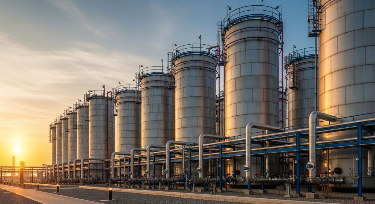
Aboveground Storage Tank Performance: A comparative analysis of the operational, economic, and safety trade-offs inherent in selecting aboveground containment over underground alternatives for industrial liquid storage.
Advantages
- Ease of visual inspection and routine maintenance access.
- Lower initial capital expenditure compared to double-walled underground tanks.
- Simplified leak detection and containment via secondary bunding or dikes.
- Ability to accommodate larger volumes and higher flow rates.
- Reduced risk of soil contamination from undetected subsurface leaks.
Disadvantages
- Susceptibility to atmospheric corrosion and environmental degradation.
- Higher vulnerability to external physical damage or fire hazards.
- Significant land footprint requirements for safety spacing and dikes.
- Thermal expansion issues requiring complex piping flexibility analysis.
- Requirement for specialized fire suppression and cooling systems.
Industrial Storage Implementation: The strategic deployment of large-scale containment solutions across diverse sectors to manage feedstock, intermediate products, and final output storage requirements.
Refinery Crude Oil Storage
Refineries utilize massive floating-roof tanks to minimize vapor space and reduce volatile organic compound emissions. These tanks are designed to handle high-throughput cycles, requiring robust internal seals and high-integrity shell plates to withstand constant level fluctuations.
Chemical Feedstock Buffering
In chemical processing plants, tanks act as critical buffers to ensure continuous production despite supply chain variability. These vessels often require specialized internal linings or stainless steel construction to prevent product contamination and resist chemical attack from aggressive reagents.
Firewater Reserve Systems
Industrial safety protocols mandate dedicated firewater storage tanks to ensure a reliable supply for emergency suppression systems. These tanks are typically designed for long-term static storage, requiring advanced cathodic protection to prevent internal corrosion of the steel shell.
Selecting the correct material and design thickness for Aboveground Storage Tanks requires a rigorous evaluation of the product stored, the ambient temperature, and the specific design pressure. As a piping engineer, I emphasize that the API 650 standard provides the baseline for these calculations, specifically focusing on the “one-foot method” for shell design. This method assumes that the hoop stress is highest at a point one foot above the bottom of each shell course, allowing for a tapered thickness profile that optimizes material usage without compromising structural integrity.
The table below outlines the critical design variables that dictate the structural requirements for carbon steel tanks. When reviewing these parameters, ensure that the corrosion allowance is added to the calculated minimum thickness, as this is a frequent point of failure during third-party inspections. Always verify that the material toughness meets the requirements of Figure 5-1 in the standard, especially for tanks operating in cold climates where brittle fracture is a significant risk factor.
| Parameter | Standard Reference | Design Consideration |
|---|---|---|
| Shell Thickness | API 650 Section 5.6 | One-foot method for hoop stress |
| Bottom Plate | API 650 Section 5.4 | Minimum 6mm nominal thickness |
| Roof Design | API 650 Section 5.10 | Fixed vs. Floating roof selection |
By adhering to these specific design parameters, engineers can ensure that the tank shell remains within the allowable stress limits defined by the material yield strength. Failure to account for the hydrostatic head pressure or the specific gravity of the stored liquid often leads to premature buckling or weld seam failure during the initial hydro-test phase.
The following matrix maps the essential technical entities involved in the lifecycle of Aboveground Storage Tanks. Understanding the relationship between these components and the governing standards is vital for maintaining compliance during the procurement, fabrication, and erection phases. In my experience, the most successful projects are those where the engineering team maintains a clear traceability matrix between the design specifications and the actual site-installed components.
This mapping helps in identifying potential bottlenecks in the supply chain or quality control processes. For instance, the welding procedure specifications (WPS) must be cross-referenced with the material test reports (MTR) to ensure that the heat-affected zones meet the impact testing requirements mandated by the project specifications. Use this matrix as a foundational tool for your project documentation and quality assurance audits.
| Entity | Acronym | Standard |
|---|---|---|
| Welding Procedure Specification | WPS | ASME BPVC IX |
| Non-Destructive Examination | NDE | ASME BPVC V |
| Material Test Report | MTR | ASTM A36/A516 |
This matrix serves as a high-level overview of the regulatory landscape. Always consult the latest revisions of the referenced standards, as industry practices regarding safety and environmental containment are subject to frequent updates and regional legislative changes.
Site verification is the most critical phase in the construction of Aboveground Storage Tanks. Before any steel plate is positioned, the foundation must be inspected for levelness and soil bearing capacity. I have seen projects delayed by weeks because the foundation settlement was not monitored during the initial loading phase. Use this checklist to ensure that every stage of the erection process meets the stringent requirements of API 650.
- Foundation Levelness: Verify that the foundation is within the tolerance of 3mm in 3 meters, as per API 650 Annex B.
- Plate Alignment: Ensure that the shell plates are properly beveled and aligned to prevent excessive root opening during the welding process.
- Weld Inspection: Perform 100% visual inspection of all fillet and butt welds, followed by vacuum box testing on the bottom plate lap joints.
- Hydro-test Preparation: Confirm that all nozzles are blinded and the tank is properly vented before filling with water to prevent vacuum collapse.
- Settlement Monitoring: Install survey markers around the tank perimeter to record elevation changes during the hydro-test.
Following this checklist ensures that the structural integrity of the tank is maintained from the first weld to the final commissioning. Remember that the hydro-test is not just a leak test; it is a structural validation of the entire tank system under full design load. Any deviation from the specified tolerances must be documented and signed off by the lead structural engineer before proceeding to the next construction phase.
Problem: Unexpected Shell Buckling During Hydro-test
- Inadequate venting during the filling process caused a partial vacuum.
- The shell thickness was calculated based on incorrect specific gravity data.
- Wind loads were not adequately considered during the empty-tank phase.
- Foundation settlement exceeded the allowable limits during the initial fill.
Outcome: Successful Remediation and Structural Integrity
- Implemented a secondary venting system to prevent vacuum formation.
- Re-calculated shell thickness using the actual product density.
- Installed stiffening rings to increase the buckling resistance of the shell.
- Achieved full certification after a successful re-test of the tank.
This case study highlights the importance of accurate data input during the design phase. My recommendation is to always perform a sensitivity analysis on the specific gravity of the stored product. If there is any chance that the product density could increase, the tank design must account for this potential change to avoid costly field modifications or structural failure.
Frequently Asked Engineering Questions
What is the primary purpose of the API 650 standard?
- Structural integrity under hydrostatic and seismic loads.
- Standardized safety protocols for hazardous material containment.
- Uniformity in quality control and inspection procedures.
- Long-term reliability in diverse environmental conditions.
How does the one-foot method work for shell design?
- Assumes the hoop stress is at its maximum at this specific elevation.
- Allows for the optimization of steel plate thickness across the tank height.
- Reduces material costs while maintaining safety margins.
- Is applicable for tanks with a diameter up to 200 feet.
Why is vacuum box testing required for tank bottoms?
- It provides a non-destructive way to verify weld tightness.
- It identifies pinhole leaks that are invisible to the naked eye.
- It prevents environmental contamination from sub-surface leaks.
- It is a mandatory requirement under API 650 for all bottom plate welds.
What factors influence the choice of tank roof type?
- Vapor pressure of the liquid (high volatility requires floating roofs).
- Emission control requirements (floating roofs minimize VOC emissions).
- Cost of installation and long-term maintenance.
- Climate conditions, such as heavy snow or rainfall.
How is corrosion allowance determined for tank shells?
- The chemical nature and corrosivity of the stored product.
- The expected design life of the tank (typically 20 to 30 years).
- The presence of internal linings or cathodic protection systems.
- Historical data from similar tanks in the same service environment.
What are the risks of improper hydro-test procedures?
- Vacuum collapse due to inadequate venting during drainage.
- Foundation failure caused by uneven soil bearing pressure.
- Weld seam rupture due to excessive hydrostatic head pressure.
- Brittle fracture if the water temperature is below the material’s transition temperature.
📚 Recommended Resources: Aboveground Storage Tanks
Read these Guides
🎓 Advanced Training
Complete Course on
Piping Engineering
Check Now
Key Features
- 125+ Hours Content
- 500+ Recorded Lectures
- 20+ Years Exp.
- Lifetime Access
Coverage
- Codes & Standards
- Layouts & Design
- Material Eng.
- Stress Analysis
