Table of Contents
Storage Tank Construction Method Statement: Step-by-Step Engineering Guide
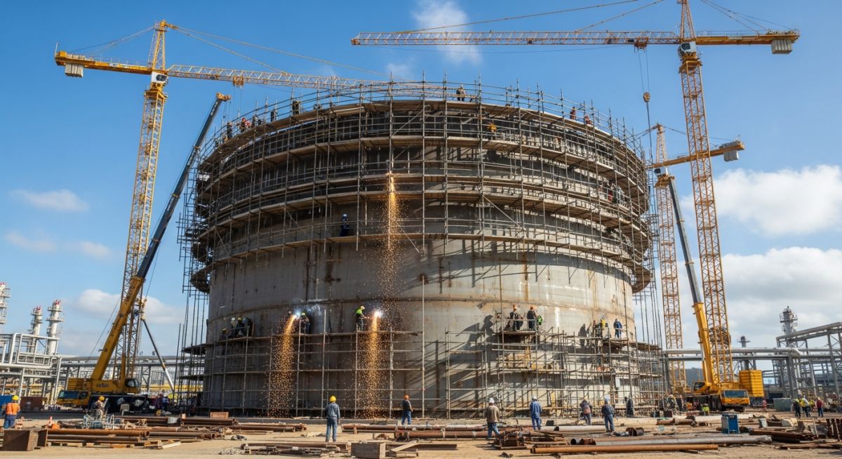
In my 20 years of managing heavy industrial construction projects, I have seen too many tank erection projects stall due to poor planning. A storage tank is not just a giant metal bucket; it is a highly engineered structure subject to massive hydrostatic and environmental loads. When you are erecting a structure that will hold millions of gallons of hazardous or flammable liquids, there is zero room for error. This guide outlines the exact, field-tested method statement I use to ensure structural integrity, weld quality, and safety from the ground up.
- Mastering the foundation levelness tolerances to prevent localized shell buckling.
- Choosing between the conventional bottom-to-top and the safer hydraulic jacking erection methods.
- Implementing the correct welding sequence to minimize residual stresses and distortion.
- Executing hydrostatic testing safely using calculated filling rates and settlement monitoring.
Executing the Storage Tank Construction Method Statement
Tank Construction Sequence: The systematic execution of foundation verification, plate layout, shell erection, and welding sequences ensures structural compliance with API Standard 650.
The foundation is the bedrock of your tank’s structural integrity. Before a single steel plate is delivered to the site, the concrete ring wall or asphalt pad must be thoroughly surveyed. According to API Standard 650 Annex B, the foundation must be level within plus or minus 1/8 inch (3 mm) in any 30 feet (9 meters) of circumference, and the maximum total deviation around the entire circumference must not exceed plus or minus 1/4 inch (6 mm).
Shell Plate Thickness Calculations
To understand the structural demands during erection, we must calculate the required shell plate thickness. Under API 650, the One-Foot Method is commonly used for tanks up to 200 feet in diameter. The design shell thickness (td) is calculated using the following formula:
Where:
D = Nominal tank diameter, in feet.
H = Design liquid level, in feet.
G = Design specific gravity of the stored liquid.
Sd = Allowable stress for the design condition, in pounds per square inch (psi).
CA = Corrosion allowance, in inches.
Let us run a real-world calculation for a medium-sized crude oil storage tank:
– Diameter (D) = 120 feet
– Height (H) = 48 feet
– Specific Gravity (G) = 0.9
– Allowable Stress (Sd) = 23,200 psi (for ASTM A516 Grade 70 steel)
– Corrosion Allowance (CA) = 0.125 inches
td = (2.6 * 120 * 47 * 0.9) / 23200 + 0.125
td = (13197.6) / 23200 + 0.125
td = 0.569 + 0.125 = 0.694 inches (approx. 17.6 mm)
Therefore, the bottom shell course must have a nominal thickness of at least 3/4 inch (19 mm) to satisfy both design and corrosion requirements.
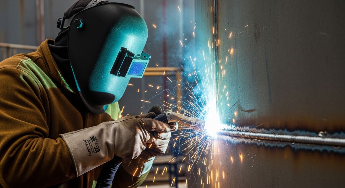
Never weld the horizontal seams of the shell plates before completing the vertical seams of that same course. Welding the horizontal seams first locks the plates in a rigid state, preventing natural shrinkage during vertical welding. This leads to severe peaking, banding, and high residual stresses that can cause catastrophic brittle fracture during hydrostatic testing.
Erection Methodologies: Jacking vs. Conventional
In my practice, I prefer the hydraulic jacking method (top-to-bottom) over the conventional crane method (bottom-to-top) for tanks under 150 feet in diameter. The jacking method allows all shell welding, roof assembly, and structural fitting to occur at ground level. This eliminates the safety hazards of working at heights and reduces wind-load vulnerability during construction.
The following tables outline the standard inspection intervals, weld joint configurations, and technical specifications required during the execution of a storage tank construction method statement.
| Shell Course | Nominal Thickness (mm) | Weld Joint Type | NDT Method | Acceptance Criteria |
|---|---|---|---|---|
| Course 1 (Bottom) | 18.0 to 22.0 | Double-V Butt Weld | 100% Radiography (RT) | API 650 Sec. 8.1 |
| Course 2 | 14.0 to 16.0 | Double-V Butt Weld | Spot Radiography | API 650 Sec. 8.1 |
| Course 3 | 10.0 to 12.0 | Single-V Butt Weld | Spot Radiography | API 650 Sec. 8.1 |
| Course 4 (Top) | 8.0 to 10.0 | Single-V Butt Weld | Visual + Magnetic Particle | ASME Sec. V |
| Entity / Acronym | Technical Definition | Physical Parameter / Value | Standard Reference |
|---|---|---|---|
| WPS / PQR | Welding Procedure Specification & Record | Tensile & Bend Test Qualified | ASME Section IX |
| Vacuum Box | Bottom plate leak testing method | Gauge vacuum of 21 to 35 kPa | API 650 Sec. 8.6 |
| Plumbness | Out-of-plumbness limit of total height | H / 200 maximum deviation | API 650 Sec. 7.5.2 |
| Peaking | Localized vertical weld distortion | 13 mm max using 900 mm sweep | API 650 Sec. 7.5.4 |
Verifying Storage Tank Construction Method Statement Steps
Quality Control Checklist: A systematic field verification protocol ensures that every phase of tank fabrication, from plate alignment to final non-destructive testing, complies with API 650 and project specifications.
Before signing off on any construction phase, the QA/QC inspector must verify the following parameters on-site. Use this checklist as your primary gatekeeping tool during execution.
-
Foundation Levelness: Verify concrete ring wall elevation profile. Ensure maximum deviation is within 6 mm across the entire circumference.
-
Bottom Plate Fit-up: Check lap joint overlap (minimum 5 times plate thickness or 25 mm, whichever is larger) before tack welding.
-
Welder Qualifications: Confirm all structural and pressure-retaining welders hold valid ASME Section IX certifications.
-
Vacuum Box Testing: Perform 100% vacuum box testing on all bottom lap welds using a soap solution at 21 to 35 kPa vacuum.
-
Shell Plumbness & Roundness: Measure verticality at 45-degree intervals. Ensure out-of-plumbness does not exceed H/200.
-
Hydrostatic Test Readiness: Verify all NDT is complete, temporary attachments are removed, and settlement markers are installed.
Field Case Study: Real-World Application
During the construction of a 150,000-barrel crude oil storage tank in a coastal refinery, the contractor attempted to accelerate the schedule. They welded the horizontal seams of the third and fourth shell courses before completing the vertical seams. This incorrect sequence locked in thermal stresses, resulting in severe “peaking” at the vertical joints that exceeded the 13 mm limit allowed by API 650. The shell profile looked wavy, and there was a high risk of localized buckling under hydrostatic load.
I ordered an immediate halt to all welding activities. We utilized carbon arc gouging to completely remove the locked-in horizontal welds around the distorted courses. We then re-aligned the vertical joints using key plates, wedges, and strongbacks. The vertical seams were welded first, allowing the plates to shrink naturally. Once the vertical welds passed radiographic testing, the horizontal seams were re-welded. The final sweep measurements showed peaking was reduced to less than 6 mm, well within code limits, saving the client from a potential catastrophic failure.
My direct recommendation for any tank erection project is to maintain a strict QA/QC presence on the tank floor. Never let schedule pressures dictate the welding sequence. The laws of metallurgy and thermal expansion are unforgiving.
Frequently Asked Engineering Questions
What is the maximum allowable foundation settlement during hydrostatic testing?
Why is vacuum box testing preferred for bottom plate welds?
What are the primary advantages of the hydraulic jacking method?
How does wind girder installation fit into the erection sequence?
What is the standard filling rate during a hydrostatic test?
Can we use pneumatic testing instead of hydrostatic testing?
===
Complete Course on
Piping Engineering
Check Now
Key Features
- 125+ Hours Content
- 500+ Recorded Lectures
- 20+ Years Exp.
- Lifetime Access
Coverage
- Codes & Standards
- Layouts & Design
- Material Eng.
- Stress Analysis

📚 Recommended Resources: storage tank construction method statement
Related posts:
![A mechanical sucker rod pumpjack operating in an oil field at sunset]()
What is Sucker Rod Pump System in Oil Production?
![Piping material engineer reviewing technical specifications on a tablet in an industrial plant.]()
How a Piping Material Engineer Drives Industrial Project Success
![Industrial refinery plant showing various types of static equipment]()
What is Static Equipment? Types and List of Static Equipments
![Side-by-side comparison of industrial process piping and power plant steam piping systems.]()
Differences Between ASME B31.3 and B31.1: B31.3 vs B31.1
![Cutaway diagram of a globe control valve highlighting the internal valve trim components]()
What is a Valve Trim? Types, Components, and Selection
![Towering steel cold box structure at an industrial cryogenic air separation unit.]()
What is a Cold Box in Cryogenic Plant Systems?