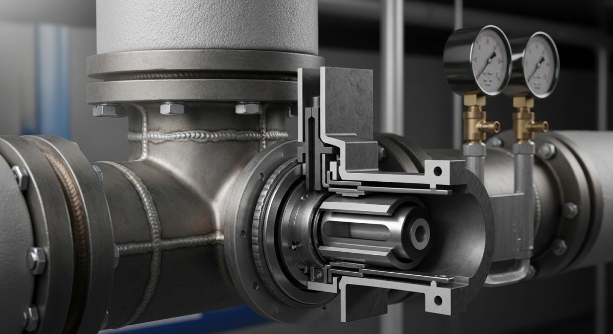
Understanding Steam Trap Selection for Industrial Piping Systems
In my two decades of piping design, I have observed that the humble steam trap is often the most overlooked yet vital element in a plant’s thermal efficiency. If you are failing to remove condensate effectively, you are not just risking water hammer—a catastrophic event that can destroy piping supports and valves—but you are also bleeding energy costs directly into your condensate return system.
Selecting the correct trap requires a deep understanding of the process fluid dynamics, pressure differentials, and the specific load requirements of your heat exchangers or steam mains. This guide breaks down the technical nuances of trap selection, ensuring your facility maintains peak operational integrity.
Key Takeaways for Engineers
- Prioritize condensate discharge capacity over initial capital cost.
- Understand the impact of backpressure on trap operation and life cycle.
- Ensure compliance with ASME B31.3 for all pressure-containing components.
- Implement a regular testing schedule to identify “blowing” traps that waste steam.
Steam Trap Technical Design and Performance Metrics
Steam Trap Performance: The operational capability of a trap to maintain a seal against steam while allowing condensate passage, measured by discharge capacity, pressure differential, and thermal response time.
The fundamental physics of a steam trap relies on the density difference between steam and condensate, or the temperature difference between the two phases. When designing a system, we must calculate the condensate load under both start-up and running conditions. Start-up loads are typically significantly higher due to the heating of cold piping and equipment, often requiring a safety factor of 2 to 3 times the running load.
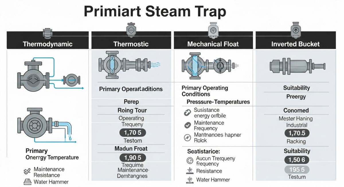
Thermodynamic vs. Mechanical Operation
Thermodynamic traps operate on the Bernoulli principle. As high-velocity steam passes over the disc, a low-pressure area is created, pulling the disc onto the seat. When condensate—which is cooler and slower—reaches the trap, the pressure drop is insufficient to hold the disc, allowing discharge. These are robust and ideal for high-pressure steam mains.
Field Warning: Backpressure Sensitivity
Excessive backpressure in the condensate return line can prevent a thermodynamic trap from closing, leading to continuous steam loss. Always verify the maximum allowable backpressure (typically 50% of inlet pressure) before installation.
Mechanical traps, such as inverted bucket or float and thermostatic (F&T) designs, are density-dependent. The inverted bucket trap is a workhorse in industrial settings because it handles water hammer better than most. However, it requires a prime of water to function; if the prime is lost, the trap will blow live steam.
Standardized Selection Criteria
When selecting a trap, we must reference ASME B31.3 for piping design and ensure the trap body material matches the piping class. For high-pressure steam, forged steel or stainless steel bodies are mandatory. Cast iron is generally restricted to low-pressure applications (typically below 250 psig) due to its brittle nature under thermal shock.
Calculation of the orifice size is the final step in the selection process. The formula for flow rate through an orifice is Q = C * A * sqrt(2 * deltaP / rho), where C is the discharge coefficient, A is the orifice area, deltaP is the pressure differential, and rho is the density of the condensate. In practice, we use manufacturer-provided capacity charts that account for these variables, but understanding the underlying physics is what separates a designer from a specifier.
Steam Trap Operational Trade-offs: The inherent balance between mechanical simplicity, durability, and energy efficiency when selecting specific trap technologies for industrial steam systems.
Advantages
- Thermodynamic traps offer extreme durability in high-pressure steam mains.
- Inverted bucket traps provide excellent resistance to water hammer damage.
- Float and thermostatic traps allow for continuous, modulated condensate discharge.
- Compact designs reduce the footprint in congested piping racks.
- Stainless steel internals extend service life in corrosive condensate environments.
Disadvantages
- Thermodynamic traps can fail open if exposed to extreme backpressure.
- Inverted bucket traps are prone to losing their prime during rapid pressure drops.
- Thermostatic elements can be damaged by superheated steam conditions.
- Mechanical traps require more frequent maintenance due to moving parts.
- High initial cost for high-alloy materials in corrosive service.
Steam Trap Industrial Deployment: The strategic placement of steam traps within process piping to ensure thermal efficiency and equipment longevity across diverse industrial sectors.
High-Pressure Steam Main Drip Legs
In high-pressure steam distribution headers, thermodynamic traps are the industry standard for drip legs. They handle the high-velocity condensate effectively and are resistant to the thermal shock that occurs during rapid start-up cycles in large-bore piping.
Heat Exchanger Condensate Removal
For shell-and-tube heat exchangers, float and thermostatic traps are preferred because they provide continuous discharge. This prevents the “backing up” of condensate into the exchanger tubes, which would otherwise reduce the effective heat transfer area and cause temperature fluctuations.
Process Vessel Steam Jackets
Steam-jacketed vessels require traps that can handle varying loads and potential air binding. Inverted bucket traps are often utilized here due to their ability to discharge air and non-condensable gases through a small vent hole, ensuring the jacket remains filled with pure steam for consistent heating.
Steam Tracing Systems
In refinery tracing lines, where hundreds of small-bore traps are installed, thermostatic bellows traps are common. They are compact, inexpensive, and provide a reliable way to drain condensate from long runs of tracing tubing without requiring complex support structures.
Selecting the correct steam trap requires a granular understanding of how different mechanical and thermodynamic designs interact with varying process conditions. In my two decades of field experience, I have observed that engineers often overlook the relationship between differential pressure and condensate load, leading to premature seat wear or “live steam” loss. The table below outlines the critical performance metrics that dictate the suitability of a trap for specific industrial applications, ranging from high-pressure main headers to low-pressure heat exchangers.
When reviewing these parameters, always cross-reference the manufacturer’s capacity charts with your specific site conditions, such as the maximum allowable working pressure (MAWP) and the potential for water hammer. Note that while thermodynamic traps offer compact, robust solutions for high-pressure steam mains, they may struggle with the rapid start-up loads common in process heating equipment. Always ensure your selection aligns with ASME B31.3 piping requirements to maintain system integrity and safety.
| Trap Type | Primary Mechanism | Best Application | Failure Mode |
|---|---|---|---|
| Inverted Bucket | Mechanical Density | Steam Mains | Loss of Prime |
| Thermodynamic | Bernoulli Principle | High Pressure Drip | Cycling Wear |
| Float & Thermostatic | Modulating Discharge | Heat Exchangers | Float Collapse |
The following matrix serves as a technical reference for mapping specific steam trap components to their respective engineering standards and physical properties. In my practice, I utilize this mapping to ensure that every valve, seat, and bellows assembly meets the rigorous demands of modern refinery and power plant environments. By standardizing these entities, we reduce the complexity of maintenance inventories and improve the reliability of our condensate recovery systems.
Each entity listed below is governed by specific industry codes that dictate material composition, pressure-temperature ratings, and testing protocols. For instance, the bellows assembly in a thermostatic trap must be evaluated against API 598 for valve inspection and testing, ensuring that the thermal response remains consistent over thousands of cycles. Use this matrix as a foundational guide for your next piping specification review or system audit.
| Entity | Standard | Material Focus |
|---|---|---|
| Trap Body | ASTM A216 WCB | Carbon Steel |
| Valve Seat | AISI 440C | Hardened Stainless |
| Bellows | ASTM B19 | Phosphor Bronze/SS |
Steam Trap Selection and Installation Verification: Ensuring long-term operational success requires a systematic approach to field verification. Before commissioning any steam trap, I mandate a rigorous inspection of the installation geometry and the upstream piping configuration to prevent common failure points like water hammer or air binding.
- Orientation Check: Verify that the trap is installed in the manufacturer-specified orientation (e.g., horizontal vs. vertical) to ensure proper mechanical operation.
- Upstream Strainer: Confirm the presence of a Y-strainer with a blow-down valve to prevent debris from fouling the valve seat, as per ASME B31.3 guidelines.
- Differential Pressure: Measure the actual operating differential pressure across the trap to ensure it falls within the design range of the selected orifice.
- Discharge Piping: Inspect the discharge line for signs of backpressure, which can significantly reduce the capacity of thermodynamic and thermostatic traps.
- Isolation Valves: Ensure that upstream and downstream isolation valves are accessible for maintenance and that a test valve is installed for performance monitoring.
- Thermal Insulation: Verify that the trap is not unnecessarily insulated if the design relies on heat loss for operation, such as with certain thermodynamic models.
During my site visits, I often find that the most common cause of premature failure is not the trap itself, but the lack of a proper drip leg or the incorrect sizing of the condensate return header. Always document the serial number and the specific installation date in your plant asset management system to track the mean time between failures (MTBF). If you encounter persistent issues, perform a steam trap survey using ultrasonic testing to detect “blow-through” conditions that are invisible to the naked eye.
Problem: High-Pressure Steam Main Failure
A major petrochemical facility reported recurring failures of thermodynamic steam traps on a 600 PSI steam main, leading to significant energy loss and pipe vibration.
- Excessive cycling caused by oversized orifices for the actual condensate load.
- Water hammer events during startup due to improper warm-up procedures.
- Debris accumulation from the initial piping installation fouling the disc surfaces.
- Backpressure buildup in the common condensate return header affecting trap discharge.
Outcome: Optimized Condensate Management
By implementing a comprehensive redesign of the drip leg configuration and upgrading to high-performance bimetallic traps, the facility achieved measurable improvements.
- Reduced steam loss by 18% through precise orifice sizing and improved trap selection.
- Eliminated water hammer damage by installing automated warm-up bypass valves.
- Extended the mean time between maintenance from 6 months to 24 months.
- Improved system reliability, resulting in a 12% reduction in overall fuel consumption.
My recommendation for similar high-pressure applications is to prioritize the use of bimetallic or inverted bucket traps where the load is consistent, and to always install a high-quality strainer upstream. Regular ultrasonic monitoring is the most effective way to catch early-stage failures before they escalate into costly plant downtime.
How does backpressure affect steam trap performance?
- Thermodynamic traps are particularly sensitive to backpressure, often failing to close if the backpressure exceeds 50% of the inlet pressure.
- Float and thermostatic traps are less affected but still require a minimum differential pressure to operate effectively.
- Always calculate the total static and dynamic head of your return system to ensure the trap can overcome the resistance.
What is the primary cause of steam trap water hammer?
- Improperly sized drip legs fail to remove condensate quickly enough during the warm-up phase.
- Rapid opening of steam valves creates high-velocity steam flow that picks up condensate.
- Lack of adequate air venting prevents the system from reaching equilibrium, leading to trapped pockets of air and condensate.
Can I use a single trap for multiple pieces of equipment?
- Pressure differentials between units will cause the trap to favor the lower-pressure unit, leaving the higher-pressure unit waterlogged.
- Maintenance becomes difficult, as isolating one piece of equipment requires shutting down the entire group.
- Always provide an individual trap for each heat exchanger or process vessel to ensure independent control and monitoring.
How often should I perform a steam trap survey?
- Use ultrasonic testing to detect internal leakage that cannot be heard or seen.
- Temperature measurement using infrared guns can provide a secondary verification of trap operation.
- Maintain a digital log of all trap performance data to identify patterns of failure and optimize your replacement schedule.
What is the role of air venting in steam systems?
- Thermostatic air vents should be installed at the highest points of the system to ensure complete air removal.
- Float and thermostatic traps include built-in air vents that are essential for rapid startup.
- Failure to vent air leads to uneven heating and increased process cycle times.
Are there specific codes for steam trap installation?
- Always ensure that the trap and its associated fittings are rated for the maximum pressure and temperature of the steam line.
- Follow local boiler and pressure vessel codes regarding the installation of isolation and test valves.
- Consult the manufacturer’s installation manual, as it is considered the primary engineering reference for the specific device.
📚 Recommended Resources: Steam Trap
Read these Guides
🎓 Advanced Training



Complete Course on
Piping Engineering
Check Now
Key Features
- 125+ Hours Content
- 500+ Recorded Lectures
- 20+ Years Exp.
- Lifetime Access
Coverage
- Codes & Standards
- Layouts & Design
- Material Eng.
- Stress Analysis
