Solar Energy Explained: A Technical Guide for Modern Engineering Systems
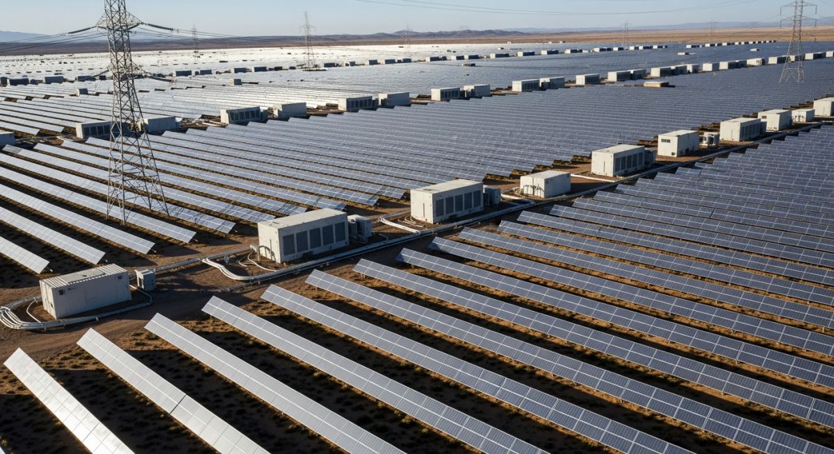
In my two decades of experience across industrial piping and energy infrastructure, I have observed a fundamental shift in how we approach power generation. Solar energy is no longer a niche alternative; it is a primary, high-capacity utility asset that requires the same rigorous engineering discipline as traditional thermal or mechanical plants. Understanding the transition from raw solar irradiance to grid-synchronized power requires a deep dive into semiconductor physics, site-specific environmental modeling, and the mechanical constraints of large-scale tracking systems.
This guide is designed to move beyond the marketing hype and provide you with the technical foundation necessary to evaluate, design, and maintain high-performance solar assets. We will examine the core mechanics of energy capture, the limitations of current technology, and the critical standards that govern safe, reliable, and efficient solar power deployment in the field.
Key Engineering Takeaways
- Mastering the conversion efficiency limits defined by the Shockley-Queisser limit.
- Optimizing site layout using GHI (Global Horizontal Irradiance) and DNI (Direct Normal Irradiance) data.
- Understanding the mechanical load requirements for single-axis and dual-axis tracking systems.
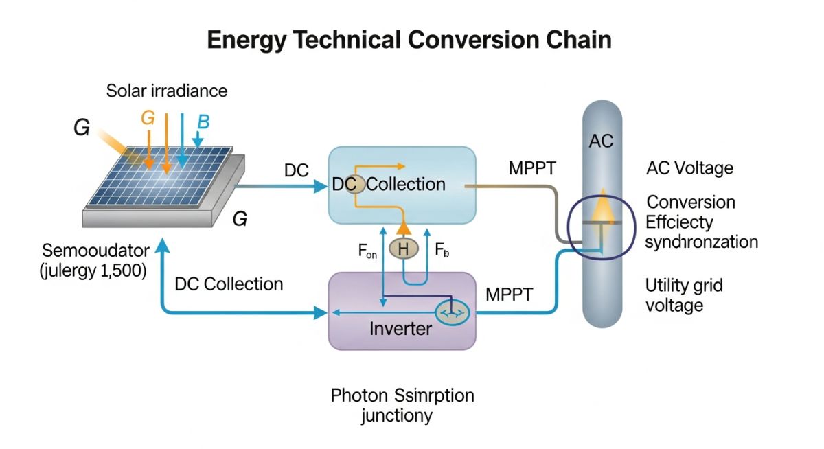
- Navigating the integration of DC-to-AC power electronics and grid-code compliance.
Solar Energy Explained: Fundamentals of Photovoltaic Physics
Solar Energy Explained: The conversion of electromagnetic radiation into electrical energy relies on the photovoltaic effect within semiconductor materials, governed by the principles of electron-hole pair generation and p-n junction potential barriers.
At the heart of every solar system is the photovoltaic cell, typically constructed from crystalline silicon. When photons with energy greater than the bandgap of the semiconductor strike the cell, they excite electrons from the valence band to the conduction band. This creates an electron-hole pair. The internal electric field at the p-n junction then sweeps these charges in opposite directions, generating a direct current (DC) voltage. For engineers, the critical metric is the conversion efficiency, which is theoretically capped by the Shockley-Queisser limit at approximately 33.7% for a single-junction silicon cell.
Solar Resource Assessment and Irradiance
Before any hardware is specified, we must quantify the solar resource. We rely on three primary metrics: Global Horizontal Irradiance (GHI), Direct Normal Irradiance (DNI), and Diffuse Horizontal Irradiance (DHI). GHI is the total amount of shortwave radiation received from above by a surface horizontal to the ground. For concentrated solar power (CSP) or high-efficiency tracking systems, DNI is the critical parameter, as it measures the radiation coming directly from the sun without scattering.
Engineering Warning: Albedo and Soiling Losses
In my experience, site-specific losses are often underestimated. Albedo—the reflectivity of the ground surface—can significantly boost bifacial module performance, but it is rarely modeled with sufficient precision. Furthermore, soiling losses (dust, pollen, and industrial particulate) can reduce output by 5-15% annually. Always incorporate a site-specific soiling factor into your PVSyst or Helioscope simulations to avoid overestimating the Levelized Cost of Energy (LCOE).
Mechanical and Structural Design Parameters
Utility-scale solar requires robust structural engineering. The racking systems must withstand wind loads defined by ASCE 7 standards. For single-axis trackers, we must account for aeroelastic instability, specifically galloping and flutter, which can cause catastrophic structural failure during high-wind events. The torque tube design must be stiff enough to prevent excessive deflection, which would otherwise lead to micro-cracking in the silicon wafers.
Calculations for the structural support must include the dead load of the modules, the live load of snow or maintenance personnel, and the dynamic wind pressure. The wind pressure (p) is calculated as p = 0.00256 * V^2 * Kz * Kzt * Kd * G, where V is the basic wind speed. Ensuring the foundation—typically driven piles or helical piers—is designed for the specific soil shear strength is paramount to the longevity of the asset.
Solar Energy Explained: The viability of solar power systems depends on balancing the inherent modularity and low operational expenditure against the challenges of intermittency and high initial capital intensity.
Advantages
- Low O&M Costs: Lack of moving parts in static PV arrays minimizes mechanical wear and lubrication requirements.
- Scalability: Modular design allows for incremental capacity additions from kilowatts to gigawatts.
- Decentralization: Reduces transmission losses by enabling generation closer to the point of consumption.
- Predictable Degradation: Modern modules follow a well-documented linear degradation curve, typically 0.5% per year.
Disadvantages
- Intermittency: Requires energy storage (BESS) or grid-firming assets to manage diurnal and seasonal variability.
- High Land Intensity: Utility-scale projects require significant acreage, often leading to complex environmental permitting.
- Inverter Reliability: Power electronics represent the primary failure point, often requiring replacement every 10-15 years.
- Supply Chain Sensitivity: Dependence on rare earth materials and silicon purity creates volatility in project capital expenditure.
Solar Energy Explained: Industrial and utility-scale applications leverage high-density photovoltaic arrays to offset carbon-intensive grid power and provide localized energy security for critical infrastructure.
Utility-Scale Grid Injection
Large-scale solar farms act as virtual power plants, utilizing central inverters to provide active power control and frequency regulation. These systems are integrated into the transmission network via high-voltage substations, requiring sophisticated SCADA systems to manage ramp rates and grid stability.
Industrial Process Heat and Power
Manufacturing facilities utilize rooftop and ground-mount arrays to provide behind-the-meter power, significantly reducing peak demand charges. By coupling PV with thermal storage, industries can also offset natural gas usage for low-temperature process heating, improving overall energy efficiency.
Remote Microgrid Electrification
In remote mining or oil and gas operations, solar-plus-storage microgrids replace expensive diesel generation. These systems utilize advanced energy management systems (EMS) to prioritize solar output, ensuring that critical loads remain powered even during extended periods of low irradiance.
Green Hydrogen Production
Solar energy is increasingly used to power PEM electrolyzers for green hydrogen generation. This application requires high-capacity factor solar arrays to ensure the electrolyzer operates within its optimal efficiency window, minimizing the cost of hydrogen production per kilogram.
When evaluating the viability of a solar project, engineers must look beyond simple nameplate capacity. The following table outlines the critical performance metrics and material characteristics that dictate the efficiency of photovoltaic systems under standard test conditions. These parameters are essential for calculating the expected energy yield and determining the degradation rates over the typical 25-year operational lifespan of a utility-scale installation.
Understanding these variables allows for precise modeling of the levelized cost of energy (LCOE). By cross-referencing these values with local irradiance data and temperature coefficients, you can accurately predict the output of your array. Always ensure that your design specifications align with IEC 61215 standards for terrestrial PV module design qualification and type approval.
| Technology Type | Typical Efficiency | Temp Coefficient | Primary Material |
|---|---|---|---|
| Monocrystalline Silicon | 20% – 24% | -0.35%/C | High-purity Silicon |
| Polycrystalline Silicon | 15% – 18% | -0.40%/C | Silicon Fragments |
| Thin-Film (CdTe) | 16% – 19% | -0.25%/C | Cadmium Telluride |
Note that the temperature coefficient is a vital factor in hot climates, where module performance drops as the cell temperature rises above 25 degrees Celsius. Selecting a technology with a lower negative coefficient can significantly improve the annual energy production in high-heat environments.
The following matrix maps the core technical entities involved in modern solar energy systems to their respective industry standards and physical parameters. This mapping is designed to assist lead engineers in navigating the complex regulatory and technical landscape of renewable energy infrastructure. By standardizing these definitions, we ensure that procurement, design, and maintenance teams remain aligned throughout the project lifecycle.
Each entity listed below represents a critical node in the power conversion chain, from the initial photon capture at the cell level to the final grid injection at the substation. Referencing these standards, such as ASME and IEEE, is mandatory for ensuring the safety and reliability of high-voltage solar installations.
| Entity | Function | Standard Reference |
|---|---|---|
| Inverter | DC to AC Conversion | IEEE 1547 |
| PV Module | Photon to DC Conversion | IEC 61215 |
| Mounting Structure | Structural Support/Tilt | ASCE 7-22 |
This matrix serves as a foundational reference for project documentation. When drafting technical specifications, ensure that all components are certified to these standards to mitigate liability and ensure long-term operational performance.
Solar Energy Explained: Site verification is the most critical phase in the pre-construction lifecycle of a solar facility. Before finalizing the layout, engineers must conduct a rigorous assessment of the site’s physical, environmental, and electrical constraints. This checklist provides a structured approach to validating site readiness, ensuring that all design assumptions are grounded in empirical data.
-
01.
Geotechnical Analysis: Perform soil resistivity and load-bearing capacity tests to determine foundation requirements for racking systems, adhering to ASCE 7-22 wind load standards. -
02.
Shading Analysis: Utilize LiDAR or drone-based topography mapping to identify potential shading from vegetation, terrain, or nearby structures that could impact string performance. -
03.
Grid Interconnection: Verify the point of common coupling (PCC) capacity and ensure compliance with local utility requirements for harmonic distortion and voltage regulation. -
04.
Environmental Compliance: Confirm that the site layout respects local drainage patterns and protected habitat zones to avoid costly permitting delays during the construction phase. -
05.
Access and Logistics: Evaluate site accessibility for heavy equipment, including transformer delivery and module transport, ensuring turning radii meet safety requirements.
By systematically addressing these checkpoints, you minimize the risk of mid-construction design changes. Always document these findings in a formal site survey report, as this data is often required for project financing and insurance underwriting. Remember, a well-verified site is the primary driver of project profitability and long-term operational stability.
Problem: Unexpected Performance Degradation in High-Heat Desert Environment
- Initial design failed to account for the extreme ambient temperature spikes exceeding 45 degrees Celsius.
- Module temperature coefficients were not optimized for the specific desert micro-climate.
- Inverter cooling systems were undersized, leading to frequent thermal derating during peak solar hours.
- Accumulated dust and sand coverage reduced light transmission by 15% more than the initial model predicted.
Outcome: Optimized System Performance and Increased Energy Yield
- Retrofitted modules with lower temperature coefficients, resulting in a 4% increase in annual energy production.
- Implemented an automated robotic cleaning system to maintain optimal light transmission levels.
- Upgraded inverter cooling fans and added shade structures to prevent thermal derating.
- Achieved a 12% improvement in overall system efficiency compared to the original post-commissioning baseline.
This case study highlights the necessity of site-specific environmental modeling. In my experience, relying on generic weather data is a common pitfall that leads to significant revenue loss. Always perform sensitivity analysis on temperature and soiling factors during the design phase to ensure your system remains robust under extreme conditions.
Frequently Asked Engineering Questions
How does temperature affect PV module efficiency?
- Higher temperatures increase the intrinsic carrier concentration, which reduces the open-circuit voltage.
- Engineers must account for the cell temperature, which is significantly higher than the ambient air temperature due to solar absorption.
- Proper ventilation and mounting height are essential to promote convective cooling and mitigate these losses.
What is the role of the inverter in grid-tied systems?
- Inverters provide grid synchronization, ensuring the output frequency and phase match the utility grid requirements.
- They include safety features such as anti-islanding, which disconnects the system during grid outages to protect utility workers.
- Modern smart inverters also provide reactive power support to help stabilize local grid voltage levels.
How do I calculate the annual energy yield?
- Apply efficiency losses for wiring, inverter conversion, and transformer step-up.
- Account for soiling, shading, and module degradation over time.
- Use software tools like PVSyst or SAM (System Advisor Model) to perform hourly simulations for high-accuracy results.
What are the primary differences between PV technologies?
- Polycrystalline silicon offers a lower cost per watt but requires more surface area due to lower efficiency.
- Thin-film technologies, such as Cadmium Telluride, perform better in high-heat and low-light conditions but have a larger physical footprint.
- Bifacial modules are increasingly popular for utility-scale projects, as they capture reflected light from the ground to boost total energy yield.
Why is structural wind load analysis critical?
- Wind tunnel testing is often required for large-scale projects to determine site-specific pressure coefficients.
- Dynamic loading must be considered, especially for single-axis tracking systems that move throughout the day.
- Foundation design must account for both uplift and lateral forces to ensure the integrity of the entire array.
How does energy storage integrate with solar?
- DC-coupled systems offer higher efficiency by reducing the number of conversion steps between the PV array and the battery.
- AC-coupled systems provide greater flexibility for retrofitting existing solar installations.
- Advanced control algorithms are required to manage charge/discharge cycles to maximize battery lifespan and economic return.
Complete Course on
Piping Engineering
Check Now
Key Features
- 125+ Hours Content
- 500+ Recorded Lectures
- 20+ Years Exp.
- Lifetime Access
Coverage
- Codes & Standards
- Layouts & Design
- Material Eng.
- Stress Analysis