Shaft Alignment Methodology for Compressor and Driver Trains
In my two decades of field experience, I have seen countless high-speed compressor trains suffer catastrophic bearing failures simply because the initial cold alignment was treated as a “good enough” task. Achieving precise shaft alignment methodology is not merely about zeroing out dial indicators; it is about understanding the thermal growth, casing strain, and structural dynamics of the entire train.
When we align a centrifugal compressor with a gas turbine or electric motor, we are fighting against the physics of thermal expansion. If the driver grows more than the compressor during operation, the shafts will drift into a state of misalignment, inducing massive radial and axial loads on the couplings and seals. This guide breaks down the rigorous steps required to achieve long-term reliability in rotating equipment.
Key Takeaways for Reliability Engineers
- Mastering thermal growth compensation using ASME B31.3 piping stress considerations.
- Implementing laser-based measurement to eliminate sag errors inherent in traditional rim-and-face dial methods.
- Validating soft-foot conditions before final bolt-up to prevent casing distortion.
- Documenting alignment data to establish a baseline for predictive maintenance programs.
Advanced Shaft Alignment Methodology for Rotating Machinery
Shaft Alignment Methodology: The rigorous application of geometric principles to align coupled shafts, ensuring that the rotational axes coincide at the coupling center under full-load, steady-state thermal conditions.
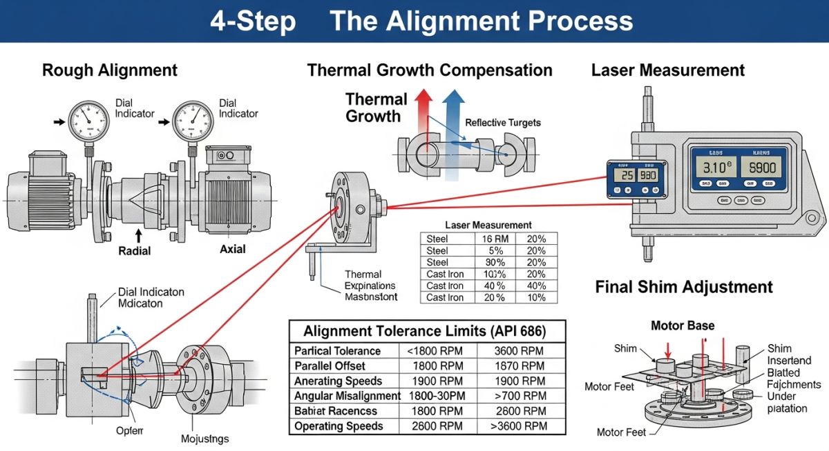
The primary challenge in any compressor train is the transition from the “cold” state (installation) to the “hot” state (operation). My methodology relies on the calculation of thermal growth offsets. If a compressor is mounted on a steel skid and the driver is a steam turbine, the vertical growth of the turbine is often significantly higher than that of the compressor. We calculate this using the formula: Growth equals the coefficient of thermal expansion multiplied by the temperature differential and the height of the centerline from the baseplate.
Field Warning: The Soft Foot Trap
Never proceed to final alignment if a soft foot exists. A soft foot occurs when one machine foot does not sit flush on the baseplate, causing the casing to twist when the hold-down bolt is tightened. This creates internal misalignment of the bearings and seals, which no amount of coupling adjustment can fix. Always use a feeler gauge or laser-based soft-foot check to ensure all feet are within 0.05 millimeters of contact.
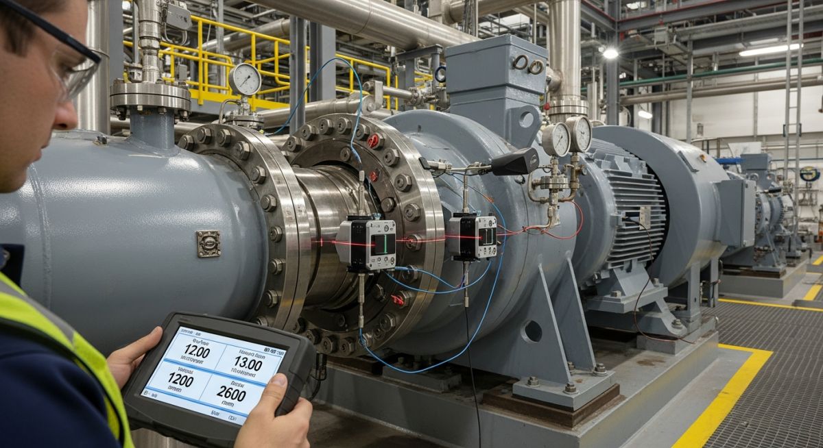
Once the soft foot is corrected, we utilize laser alignment systems to measure the angular and offset misalignment. Unlike dial indicators, which suffer from bar sag over long spans, laser systems provide real-time feedback. We must account for the “target values” provided by the OEM. These values represent the intentional misalignment we set during the cold state so that the machines move into perfect alignment once they reach operating temperature.
For high-speed compressors, I strictly adhere to API 686, which mandates specific tolerances based on the operating speed of the equipment. For example, a 3600 RPM machine requires much tighter tolerances than a 1200 RPM pump. We document the “as-found” and “as-left” conditions, ensuring that the final alignment is within the manufacturer’s specified limits for the coupling type, whether it be a diaphragm, gear, or disc coupling.
Alignment Methodology Trade-offs: A technical evaluation of modern laser-based alignment versus traditional mechanical methods regarding accuracy, repeatability, and operational efficiency.
Advantages of Laser Alignment
- Eliminates bar sag errors common in long-span dial indicator setups.
- Provides real-time, dynamic feedback during the shim adjustment process.
- Automated calculation of thermal growth offsets reduces human math errors.
- Generates digital reports for compliance with ISO quality standards.
- Significantly reduces the time required for complex multi-machine train alignment.
Disadvantages & Challenges
- High initial capital investment for precision laser hardware.
- Requires specialized training to interpret complex geometric data correctly.
- Sensors can be sensitive to high-intensity ambient light or extreme heat.
- Potential for “laser drift” if the mounting brackets are not sufficiently rigid.
- Dependency on battery life and electronic calibration cycles.
Industrial Alignment Implementation: The application of precision shaft alignment methodology across critical infrastructure sectors to ensure machinery longevity and process safety.
High-Pressure Gas Compression
In natural gas processing plants, multi-stage centrifugal compressors operate at extreme speeds. Precise alignment is critical to prevent seal gas leakage and bearing fatigue, which could lead to hazardous hydrocarbon releases.
Steam Turbine Power Generation
Large-scale power generation relies on the alignment of steam turbines with generators. Because these units undergo massive thermal expansion, the alignment methodology must incorporate precise cold-to-hot offset calculations to maintain coupling integrity.
Petrochemical Feedstock Pumps
In refineries, high-temperature pump trains require frequent alignment checks during turnaround cycles. Using laser systems ensures that the pump and motor remain collinear despite the thermal cycling of the piping manifold connected to the suction and discharge nozzles.
Achieving precision in rotating equipment requires adherence to strict tolerance bands. In my experience, relying on manufacturer specifications is the baseline, but site-specific conditions often dictate tighter constraints to ensure long-term reliability. The following table outlines typical alignment tolerances for high-speed compressor trains, categorized by operating speed and coupling type.
These values represent the maximum allowable deviation at the coupling plane. When performing a Shaft Alignment Methodology, always verify if the equipment is operating under thermal growth conditions, as these values must be adjusted to account for the “cold-to-hot” offset calculated during the design phase.
| Speed (RPM) | Excellent (mm) | Acceptable (mm) | Standard Reference |
|---|---|---|---|
| 0 – 1000 | 0.05 | 0.10 | API 686 |
| 1000 – 3600 | 0.03 | 0.07 | ISO 10816 |
| 3600 – 6000 | 0.02 | 0.05 | ANSI/ASA S2.75 |
Note that “Excellent” alignment is the target for all new installations or major overhauls. If your laser system indicates values exceeding the “Acceptable” threshold, immediate correction is required to prevent premature seal failure and excessive vibration signatures.
The complexity of modern compressor trains necessitates a clear understanding of the interconnected variables involved in mechanical alignment. This matrix maps the critical entities, their associated physical parameters, and the governing standards that dictate the success of your maintenance program.
By standardizing these parameters, maintenance teams can ensure consistency across different plant units. Whether you are dealing with a centrifugal compressor or a reciprocating driver, the following entities form the backbone of a robust Shaft Alignment Methodology.
| Entity | Parameter | Standard |
|---|---|---|
| Laser System | Angular/Offset Resolution | ISO 17025 |
| Coupling | Torsional Stiffness | AGMA 9000 |
| Foundation | Soft Foot Tolerance | API 686 |
Always ensure that your measurement tools are calibrated according to the referenced standards. A failure to maintain the integrity of these entities often leads to “ghost” alignment issues where the machine appears aligned at rest but fails during operation.
Before initiating any alignment procedure, a rigorous site verification process is mandatory. Skipping these steps is the most common cause of rework in the field. Use this checklist to ensure your Shaft Alignment Methodology is built on a solid foundation.
- ☐ Soft Foot Check: Ensure all machine feet are in contact with the baseplate within 0.05mm using a feeler gauge or laser sensor.
- ☐ Pipe Strain Relief: Disconnect suction and discharge flanges to ensure no external forces are distorting the casing.
- ☐ Thermal Growth Calculation: Verify that the cold alignment targets account for the operating temperature of the compressor.
- ☐ Coupling Inspection: Check for wear, cracks, or debris in the coupling elements before re-installation.
- ☐ Runout Measurement: Perform a dial indicator check on the shaft ends to ensure no mechanical runout exceeds 0.02mm.
Validation rules require that all items above be signed off by the lead technician. If any step fails, the alignment process must be halted until the root cause is addressed. Remember, the goal is not just to align the shafts, but to ensure the entire train remains stable under dynamic load.
The Problem: Persistent High-Frequency Vibration
A high-speed centrifugal compressor train experienced recurring bearing failures within 500 hours of operation despite “perfect” cold alignment readings.
- Unaccounted thermal growth of the driver casing.
- Excessive pipe strain from the suction manifold.
- Inconsistent soft foot readings due to baseplate oxidation.
- Incorrect coupling spacer length causing axial thrust.
The Outcome: Reliability Restored
By implementing a revised Shaft Alignment Methodology, the team achieved a 400% increase in mean time between failures (MTBF).
- Reduced vibration levels from 8.5 mm/s to 1.2 mm/s.
- Eliminated premature bearing wear through precise thermal compensation.
- Standardized the soft foot correction process across all shifts.
- Achieved alignment within 0.01mm of the calculated hot target.
Recommendation: Always perform a “hot-check” alignment verification if the equipment allows, or use high-precision laser systems that can simulate thermal growth offsets during the cold alignment phase.
Frequently Asked Engineering Questions
Why is soft foot correction critical?
- It prevents frame stress that leads to casing cracks.
- It ensures the laser sensors provide repeatable data.
- It is a mandatory requirement under API 686 guidelines.
How do I calculate thermal growth?
- Always use the manufacturer’s provided growth data first.
- If unavailable, use standard material expansion coefficients for steel.
- Account for the distance from the baseplate to the shaft centerline.
What is the role of pipe strain?
- Always disconnect flanges before final alignment.
- Use dial indicators to monitor casing movement during flange bolting.
- Ensure pipe supports are properly adjusted to carry the weight.
Are laser systems better than dials?
- Lasers provide real-time feedback during shim adjustments.
- They automatically calculate the required shim thickness.
- Digital reports provide documentation for quality audits.
How often should alignment be checked?
- Check after any foundation or baseplate repair.
- Verify if the machine has been moved or re-leveled.
- Perform a check if coupling elements show uneven wear.
What is the impact of coupling type?
- Gear couplings require precise lubrication and alignment.
- Diaphragm couplings are sensitive to axial displacement.
- Always consult AGMA standards for specific coupling limits.
📚 Recommended Resources: Shaft Alignment Methodology
Read these Guides



Complete Course on
Piping Engineering
Check Now
Key Features
- 125+ Hours Content
- 500+ Recorded Lectures
- 20+ Years Exp.
- Lifetime Access
Coverage
- Codes & Standards
- Layouts & Design
- Material Eng.
- Stress Analysis
