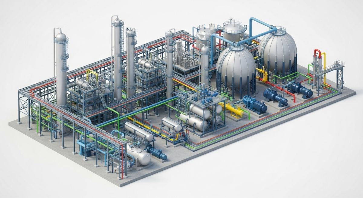
Mastering the Scope of Piping: Essential Inputs and Outputs
In my two decades of leading piping design teams, I have observed that project failures rarely stem from poor drafting skills. Instead, they originate from a breakdown in the scope of piping definition during the early FEED (Front-End Engineering Design) stages. As a piping lead, your primary responsibility is to act as the central nervous system of the plant, translating process requirements into physical reality while adhering to ASME B31.3 and other critical standards.
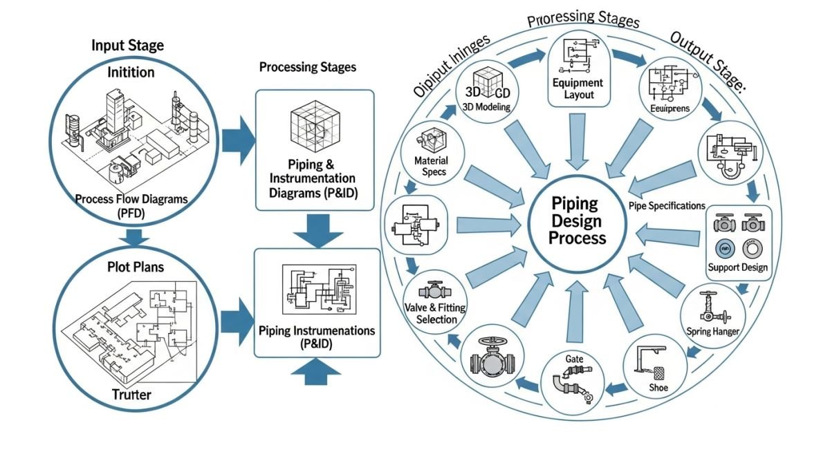
This guide dissects the precise inputs—such as P&IDs, equipment layouts, and geotechnical data—and the corresponding outputs, including stress analysis reports, isometric drawings, and MTOs. Understanding this flow is the difference between a project that finishes on schedule and one plagued by costly field rework.
Key Takeaways for Piping Leads:
- Establish a rigid document control matrix for P&ID revisions.
- Prioritize early identification of critical path equipment nozzles.
- Integrate stress analysis loops before finalizing support locations.
- Standardize the MTO (Material Take-Off) process to prevent procurement gaps.
Technical Analysis: The Scope of Piping Discipline
Piping Engineering Workflow: The structured integration of process, mechanical, and structural data into a cohesive 3D model and documentation set that satisfies pressure, temperature, and safety requirements.
The scope of piping is not merely about routing lines; it is about managing the energy and material balance of the plant. When I approach a new project, I categorize inputs into three tiers: Process, Mechanical, and Spatial. Process inputs include the P&ID, line lists, and fluid properties (density, viscosity, and corrosivity). Mechanical inputs involve equipment nozzle orientations, pump suction/discharge requirements, and vessel internals. Spatial inputs are defined by the plot plan and the structural steel envelope.
Calculations for pipe wall thickness must follow ASME B31.3, where the pressure design thickness is calculated using the formula: t = (P * D) / (2 * (S * E * W + P * Y)). Here, P is the internal design pressure, D is the outside diameter, S is the allowable stress at design temperature, E is the quality factor, W is the weld joint strength reduction factor, and Y is the coefficient for temperature. I always emphasize that the ‘Scope of Piping’ includes the rigorous verification of these variables against the actual material grade (e.g., ASTM A106 Gr. B vs. A312 TP316L).
Field Warning: The “Hidden” Scope Creep
Many junior engineers overlook the impact of thermal expansion on nozzle loads. If your piping scope does not explicitly include the coordination of nozzle loads with the mechanical equipment vendor, you will inevitably face field-fit issues during the installation phase. Always verify the allowable nozzle loads provided in the vendor data sheets against your stress analysis model.
Outputs are the tangible deliverables that drive construction. These include the 3D model, isometric drawings, piping plans, and the final MTO. A high-quality isometric must contain all bill of materials (BOM) data, weld maps, and NDT requirements. In my experience, the most successful projects are those where the piping discipline maintains a ‘live’ link between the 3D model and the MTO, ensuring that any change in routing is immediately reflected in the procurement list.
Piping Discipline Integration: The strategic balance of centralized control versus decentralized field flexibility in managing complex industrial piping systems.
Advantages
- Centralized data management ensures consistency across all disciplines.
- Early 3D modeling identifies clashes before they reach the construction site.
- Standardized MTO processes significantly reduce procurement errors and waste.
- Rigorous stress analysis prevents catastrophic failure of high-pressure lines.
- Clear scope definition improves communication between engineering and construction teams.
Disadvantages
- High initial investment in software and training for 3D modeling.
- Rigid scope definitions can sometimes stifle necessary field-level innovation.
- Over-reliance on automated MTOs can mask manual input errors.
- Complex inter-disciplinary coordination requires significant management overhead.
- Strict adherence to standards can lead to over-engineering in non-critical systems.
Industrial Piping Implementation: The practical application of piping engineering principles across diverse sectors to ensure operational safety and efficiency.
Refinery Hydroprocessing Units
In high-pressure hydroprocessing, the scope of piping involves managing extreme hydrogen service conditions. We must ensure that all piping materials are resistant to hydrogen-induced cracking and that the layout accounts for high-temperature thermal growth to protect sensitive reactor nozzles.
Cryogenic LNG Liquefaction Plants
Designing for cryogenic service requires a deep understanding of material ductility at temperatures as low as minus 160 degrees Celsius. The piping scope here focuses on specialized insulation systems and the precise calculation of contraction stresses to prevent flange leakage during cool-down cycles.
Pharmaceutical Cleanroom Piping
In the pharmaceutical sector, the scope of piping shifts toward sanitary design and high-purity requirements. We prioritize orbital welding, dead-leg minimization, and surface finish specifications to prevent bacterial growth, strictly adhering to ASME BPE standards for all process connections.
Power Plant Steam Distribution
High-pressure, high-temperature steam piping requires rigorous stress analysis to manage the massive forces generated by thermal expansion. The scope includes the design of complex spring hanger systems and expansion loops to ensure that the piping system does not exert excessive force on the turbine or boiler nozzles.
In my two decades of experience, I have found that the clarity of the Scope of Piping is directly proportional to the quality of the data exchange between disciplines. The following table outlines the critical engineering deliverables that define the boundary between mechanical, process, and structural teams. These documents serve as the primary inputs for piping stress analysis, material procurement, and final construction isometric generation.
Engineers must ensure that every document listed below is cross-referenced against the ASME B31.3 code requirements to maintain safety and regulatory compliance. Failure to synchronize these inputs often leads to significant rework during the construction phase, particularly regarding nozzle orientation and support placement.
| Deliverable Type | Primary Input Source | Engineering Standard |
|---|---|---|
| Piping & Instrumentation Diagram (P&ID) | Process Engineering | ISA 5.1 |
| Equipment Outline Drawings | Mechanical/Static Equipment | API 650/661 |
| Piping Material Specification (PMS) | Piping Materials/Metallurgy | ASME B31.3 |
| Structural Steel Layouts | Civil/Structural | AISC 360 |
By maintaining this structured approach to data management, the piping lead can effectively mitigate risks associated with inter-disciplinary interference and ensure that the final design meets all project-specific performance criteria.
The following matrix maps the technical entities involved in the Scope of Piping to their respective regulatory frameworks and physical parameters. This mapping is essential for junior and senior engineers alike to understand the hierarchy of design constraints that govern modern plant construction. Each entity represents a specific node in the engineering workflow where data must be validated for accuracy.
When reviewing these entities, consider the impact of thermal expansion and pressure transients on the overall system integrity. The integration of these parameters into 3D modeling software requires a rigorous verification process to ensure that the digital twin accurately reflects the physical reality of the piping system under operating conditions.
| Entity | Acronym | Standard Reference |
|---|---|---|
| Pressure Piping Systems | PPS | ASME B31.3 |
| Flange and Fitting Dimensions | FFD | ASME B16.5 |
| Pipe Support Standards | PSS | MSS SP-58 |
This matrix should be utilized during the initial project kickoff to align the team on the applicable codes and standards. Consistent application of these references prevents the common pitfall of mixing incompatible piping components, which is a frequent cause of field-level failures.
Verification of the Scope of Piping requires a systematic approach to ensure that the design intent is fully realized during the construction phase. In my experience, the most successful projects are those where the piping lead conducts regular site walk-downs to compare the 3D model against the physical installation. This process is not merely about visual inspection; it is about validating the engineering assumptions made during the design phase.
Field Verification Checkpoints
- Nozzle Alignment: Verify that equipment nozzle orientations match the P&ID and 3D model coordinates within the tolerances specified in ASME B31.3.
- Support Integrity: Ensure that all primary and secondary supports are installed according to the support detail drawings and that no interference exists with structural steel.
- Access and Maintenance: Confirm that valve handwheels, instrumentation, and flanges are accessible for routine maintenance and emergency operations as per the project’s human factors engineering guidelines.
- Slope and Drainage: For gravity-fed lines, verify that the required slope is maintained throughout the entire run to prevent liquid accumulation and potential water hammer events.
- Material Traceability: Check that the installed pipe and fitting materials match the project’s Piping Material Specification (PMS) and that heat numbers are recorded for all pressure-containing components.
Before signing off on any piping section, ensure that all non-destructive examination (NDE) reports are reviewed and filed. Any deviation from the approved design must be documented through a formal Management of Change (MOC) process to maintain the integrity of the plant’s documentation. By following this checklist, you minimize the risk of operational downtime and ensure long-term safety for the facility.
Problem: Excessive Vibration in High-Pressure Compressor Discharge
During the commissioning of a high-pressure gas compression station, the discharge piping experienced severe vibration, leading to premature failure of small-bore connections and instrument fittings.
- Inadequate support stiffness at the compressor discharge nozzle.
- Resonant frequency of the piping system coinciding with the compressor operating speed.
- Lack of vibration dampening measures on branch connections.
- Insufficient clearance between the piping and adjacent structural steel members.
Outcome: Successful Mitigation and System Stabilization
The engineering team implemented a comprehensive vibration mitigation strategy that restored system integrity and ensured safe, continuous operation of the compression unit.
- Installed heavy-duty structural clamps to increase the natural frequency of the piping system.
- Modified branch connections to include gusseted supports, reducing stress concentration factors.
- Performed a site-based vibration analysis to confirm that the new support configuration shifted the resonant frequency outside the operating range.
- Updated the project design standards to include mandatory vibration analysis for all high-pressure discharge lines.
My recommendation for similar projects is to perform a formal vibration assessment during the FEED (Front-End Engineering Design) stage. Relying on standard support spacing is often insufficient for high-energy piping systems, and proactive engineering is far more cost-effective than reactive field modifications.
What is the primary role of the piping lead in a project?
- Managing the inter-disciplinary data flow between process, mechanical, and structural teams.
- Overseeing the development of 3D models and ensuring that all piping layouts adhere to ASME B31.3.
- Reviewing and approving all piping deliverables, including isometrics, support drawings, and material take-offs.
- Resolving field-level interferences and managing the technical change control process throughout the project lifecycle.
How do you handle scope creep in piping design?
- Establish a clear baseline for the Scope of Piping at the start of the project.
- Document all client-requested changes in a formal register, detailing the technical justification and resource requirements.
- Communicate the impact of these changes to the project management team immediately to ensure alignment on budget and timeline.
- Avoid “gold-plating” the design by strictly adhering to the project’s defined performance requirements rather than over-engineering solutions.
What are the most common piping design errors?
- Incorrect nozzle orientation on equipment, leading to field rework and piping stress issues.
- Failure to account for thermal expansion, resulting in excessive loads on equipment nozzles.
- Inadequate clearance for maintenance, such as valve removal or instrument calibration.
- Misalignment between the Piping Material Specification (PMS) and the actual service conditions, which can lead to material degradation or catastrophic failure.
How does the Scope of Piping integrate with structural design?
- Dead loads from pipe, fluid, and insulation.
- Thermal expansion forces and moments at anchor points.
- Dynamic loads resulting from pressure surges or vibration.
- The structural team, in turn, provides the piping team with steel layouts and support locations, ensuring that the piping system is adequately braced without interfering with structural integrity.
What standards govern the Scope of Piping?
- ASME B31.3 for process piping design and construction.
- ASME B16.5 for pipe flanges and flanged fittings.
- MSS SP-58 for pipe hangers and supports.
- API 650 for welded tanks and their associated piping connections.
Why is the P&ID the most important input?
- The connectivity between all plant components.
- The required line sizes and material classes based on process conditions.
- The placement of isolation valves, control valves, and safety relief systems.
- Any deviation from the P&ID during the design phase must be formally reconciled to prevent operational hazards and ensure that the final plant configuration matches the process design intent.
📚 Recommended Resources: Scope of Piping
Read these Guides
🎓 Advanced Training



Complete Course on
Piping Engineering
Check Now
Key Features
- 125+ Hours Content
- 500+ Recorded Lectures
- 20+ Years Exp.
- Lifetime Access
Coverage
- Codes & Standards
- Layouts & Design
- Material Eng.
- Stress Analysis
