Author: Atul Singla | Senior Piping Engineer | Last Updated: May 2026
Rockwell Hardness Scale for Hardness Test
On the shop floor, I have seen entire batches get rejected just because someone selected the wrong Rockwell scale. No material failure, no metallurgical issue—just a wrong setting on the machine. That’s how sensitive Rockwell Hardness Scale testing is in real industrial conditions.
If you are working in manufacturing, piping, fabrication, or vendor inspection, understanding this test is not optional. It directly affects acceptance, quality control, and even safety of components.
Key Takeaways from Field Experience:
- Rockwell hardness depends heavily on correct scale selection (HRC, HRB, etc.)
- Surface condition and operator handling can drastically affect readings
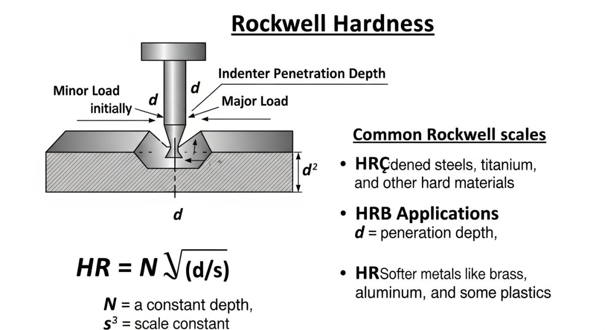
- The formula HR = N − (d/s) is simple, but field errors come from setup
- ASTM E18 is the standard you must follow for reliable results
The Rockwell Hardness Scale measures material hardness based on indentation depth under a specified load using a diamond or ball indenter. The value is calculated using HR = N − (d/s), where hardness is inversely related to penetration depth. It is widely used due to speed, simplicity, and repeatability in industrial testing.
Interactive Engineering Quiz
Q1. Rockwell hardness value is based on what primary measurement?
What is the Rockwell Hardness Test?
In my field work across fabrication yards and vendor audits, I rely on the Rockwell Hardness Scale because it gives a direct hardness number without optical measurement. The method measures indentation depth under a minor load followed by a major load using a specific indenter (diamond cone or steel/tungsten carbide ball).
The governing specification is ASTM E18. If your procedure deviates from it, your readings can’t be defended during inspections.
Types of Rockwell Hardness Tests
- HRC – Diamond cone, used for hardened steels
- HRB – 1/16" ball, used for softer steels and alloys
- HRA – Diamond cone, thin or hard coatings
- HRF, HRG – Ball indenters for soft metals like copper, aluminum
⚠ Field Warning: I have seen inspectors use HRC on low-carbon steel. The result? False low hardness → entire batch rejection. Always match scale to material hardness range.
Rockwell Hardness Test Procedure
- Prepare smooth, clean surface (no scale, rust, grinding marks)
- Apply minor load (10 kgf)
- Apply major load (60, 100, or 150 kgf)
- Hold for standard dwell time
- Release major load and measure depth
Rockwell Hardness Test Formula
HR = N − (d/s)
Where:
N = scale constant
d = depth of indentation
s = scale factor
Rockwell Hardness Scale
Each scale (A, B, C etc.) corresponds to a different indenter and load combination. In piping projects, I mostly see HRC and HRB.
Factors for Selecting Appropriate Rockwell Scale
- Material type and hardness range
- Thickness of specimen
- Surface condition
- Required accuracy
Standards for Rockwell Hardness Testing
- ASTM E18
- ISO 6508
- EN standards (project-specific)
Rockwell Hardness Test Machine
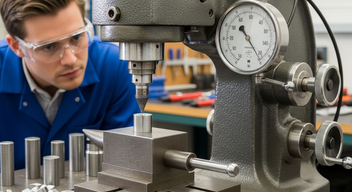
Machines can be manual or digital. In vendor shops, I always verify calibration blocks before trusting readings.
Factors Affecting Accuracy and Reliability
- Surface roughness
- Improper scale selection
- Machine calibration issues
- Operator skill
Typical Rockwell Hardness Values
| Material | Rockwell Scale | Typical Range |
|---|---|---|
| Mild Steel | HRB | 60–100 |
| Tool Steel | HRC | 50–65 |
| Aluminum | HRF | 20–60 |
Advantages of Rockwell Hardness Testing
- Fast and direct measurement
- No optical measurement required
- Minimal operator dependency (if trained)
Rockwell Hardness Test vs Brinell Hardness Test
| Criteria | Rockwell | Brinell |
|---|---|---|
| Measurement | Depth | Diameter |
| Speed | Fast | Slow |
| Accuracy (rough surfaces) | Lower | Higher |
Field Case Study: Real-World Application
Problem: During a refinery piping project, a vendor reported low hardness values on carbon steel flanges. Client flagged it as non-compliance.
I checked their test records and noticed they used HRC scale instead of HRB. That single mistake shifted readings completely.
We re-tested using correct scale, ensured polished surface, verified calibration block, and repeated measurements across multiple points.
Outcome: Hardness values matched specification → material accepted → avoided major project delay.
Field Lesson: Never trust hardness reports blindly. Always verify scale, surface prep, and calibration. One wrong setting can cost millions.
Engineering FAQs
What is the most commonly used Rockwell scale?
Why is surface preparation important?
What standard governs Rockwell testing?
Can thin materials be tested?
What causes inconsistent results?
Is Rockwell better than Brinell?
Advanced Rockwell Hardness Testing Insights (From Field Practice)
In my experience on EPC projects and vendor audits, most engineers understand the basic Rockwell Hardness Scale, but very few go deeper into the factors that actually control the accuracy and interpretation of results. On paper, the process looks simple—but on the shop floor, that’s rarely the case.
Reality Check: A Rockwell hardness number is only meaningful if test conditions are tightly controlled. Otherwise, the value is just a number—not a reliable property.
1. Indenter Selection & Wear Impact
I always verify indenter condition before trusting results. A worn diamond indenter or flattened ball can directly affect indentation depth.
- Diamond cone wear → lower HRC values
- Ball deformation → inconsistent HRB readings
- Uncalibrated indenter → systematic error across batch
2. Minimum Thickness Rule (Critical in Piping Work)
When I test pipe sections or thin components, I follow a strict rule:
Minimum thickness ≥ 10 × indentation depth
If this is ignored, the underlying support surface interferes with penetration, giving a falsely higher hardness value.
⚠ Field Failure I’ve Seen: Thin SS sheets showed HRC 40+ reading, but actual hardness was much lower. The anvil support caused incorrect measurement.
3. Spacing Between Indentations
Indentation spacing is one of the most ignored parameters in vendor shops. I follow:
- Distance between two indentations ≥ 3 × indentation diameter
- Distance from edge ≥ 2.5 × indentation diameter
Close indentations cause strain hardening overlap, which results in incorrect higher readings.
4. Effect of Surface Preparation
Surface finish directly impacts depth detection. In my inspections, I insist on:
- Grinding → fine polishing
- No paint, coating, or scale
- No decarburized layer (common after heat treatment)
⚠ Common Mistake: Testing on painted or oxidized surface. The indenter first crushes coating → false low hardness.
5. Temperature Influence
In some refinery projects, I’ve tested components right after heat treatment. That’s a serious mistake.
- Higher temperature → lower measured hardness
- Thermal expansion affects indentation depth
I always wait for components to reach ambient temperature before testing.
6. Conversion Between Hardness Scales (Use Carefully)
Many engineers convert Rockwell values to Brinell or Vickers. I avoid this unless absolutely required.
| HRC | Approx. BHN | Application |
|---|---|---|
| 20 | ~225 | Low alloy steel |
| 40 | ~375 | Heat-treated components |
| 60 | ~650 | Tool steel |
These conversions are approximate. For critical acceptance, I always test using the required scale instead of relying on conversion charts.
7. Calibration Best Practice (What I Personally Do)
Before starting inspection, I follow a simple but strict routine:
- Check machine leveling
- Verify indenter condition
- Test with certified calibration block
- Match reading within permissible tolerance (ASTM E18)
- Only then start actual testing
My Field Rule: If calibration is not verified, I don’t accept a single hardness reading—no matter who performed the test.
Complete Course on
Piping Engineering
Check Now
Key Features
- 125+ Hours Content
- 500+ Recorded Lectures
- 20+ Years Exp.
- Lifetime Access
Coverage
- Codes & Standards
- Layouts & Design
- Material Eng.
- Stress Analysis