Table of Contents
Pressure Vessel Fabrication Process Explained for Industrial Projects
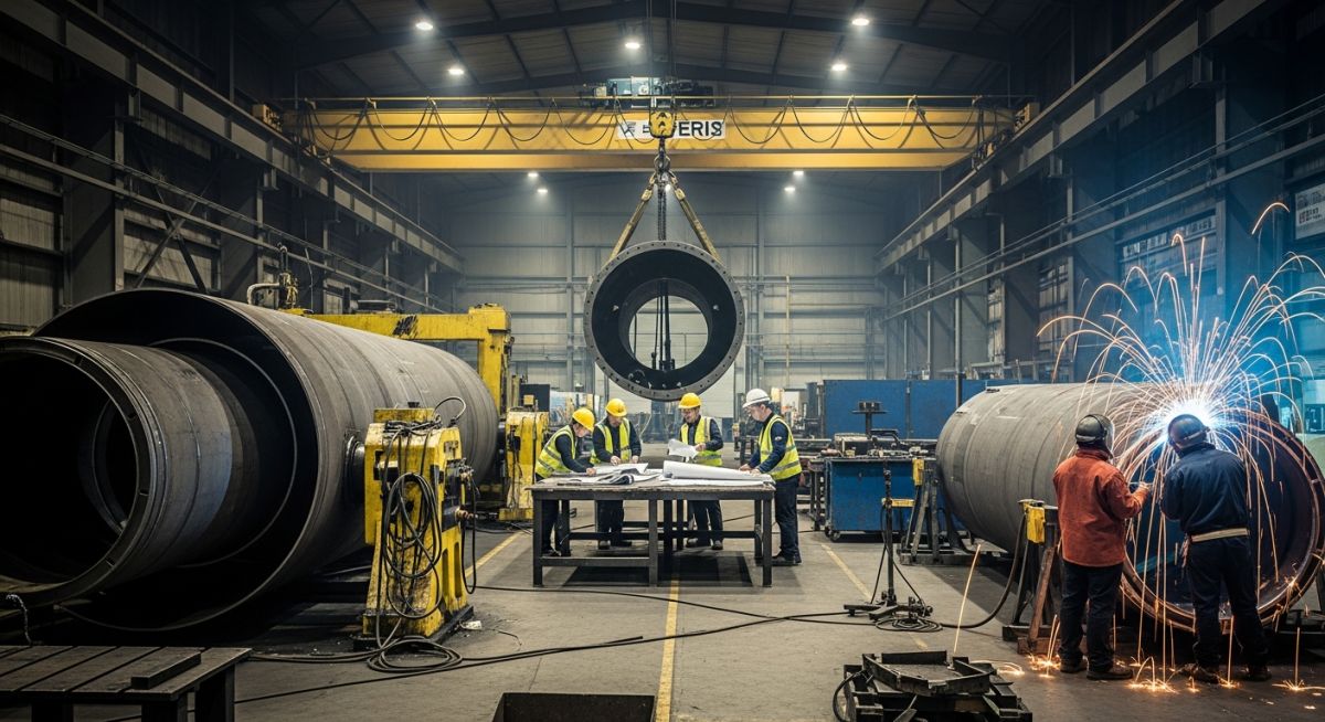
In my experience across EPC and process plant projects, pressure vessel fabrication is where theoretical design meets harsh shop-floor reality. I’ve personally seen vessels fail hydrotests due to minor welding defects and entire project schedules slip because of poor heat treatment control. That’s why I always emphasize—fabrication is not just manufacturing, it’s a disciplined engineering process governed by standards, tolerances, and inspection checkpoints.
Whether you are working on a methanol plant, refinery unit, or utility system, fabrication quality defines long-term plant reliability. The gap between a successful vessel and a rejected one often comes down to small but critical aspects like weld sequencing, rolling tolerances, or NDT coverage.
- Over 70% of fabrication issues originate from improper welding control
- PWHT mismanagement is a hidden risk for long-term vessel failure
- NDT planning must align with ASME code—not just project convenience
- Fit-up accuracy during fabrication directly impacts site installation
Interactive Engineering Quiz
Q1. Which ASME code governs pressure vessel fabrication?
Complete Course on
Piping Engineering
Check Now
Key Features
- 125+ Hours Content
- 500+ Recorded Lectures
- 20+ Years Exp.
- Lifetime Access
Coverage
- Codes & Standards
- Layouts & Design
- Material Eng.
- Stress Analysis
Pressure Vessel Fabrication Process Explained Deeply
Pressure Vessel Fabrication Process: Pressure vessel fabrication follows a controlled sequence of plate forming, welding, heat treatment, and inspection in compliance with ASME Section VIII. It ensures pressure integrity under internal or external loads by maintaining strict dimensional tolerances and weld quality assurance.
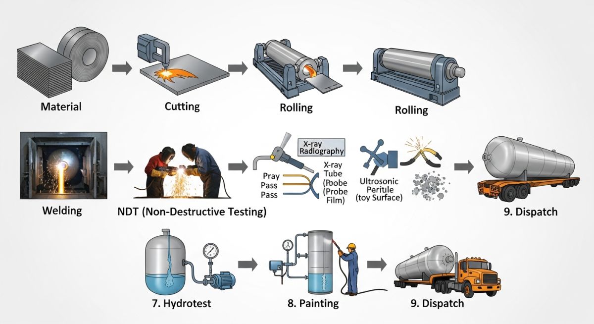
Material Preparation and Plate Rolling Control
Material Preparation: Steel plates are cut and rolled to cylindrical shapes maintaining diameter tolerance within ±1% as per fabrication standards. Rolling stress and spring-back must be controlled to avoid weld misalignment.
In real shop conditions, I always check rolling deviation using template gauges. Even a 5 mm mismatch can create major fit-up issues during longitudinal seam welding.
Welding Process Control and Heat Input
Welding in Fabrication: Welding joins shell sections and nozzles using qualified WPS ensuring penetration, reinforcement, and defect-free joints under ASME compliance.
Heat Input Formula:
Heat Input (kJ/mm) = (Voltage × Current × 60) / (1000 × Welding Speed)
For example:
Voltage = 25V, Current = 200A, Speed = 250 mm/min
Heat Input = (25 × 200 × 60) / (1000 × 250) = 1.2 kJ/mm
In my fabrication audits, uncontrolled heat input leads to distortion and residual stresses. Maintaining optimum heat input is critical.
Post Weld Heat Treatment Importance Explained
Heat Treatment: PWHT reduces residual stresses and improves toughness using controlled heating cycles as per material thickness and code requirements.
Typical PWHT Range:
- Temperature: 580°C to 620°C for carbon steel
- Holding Time: 1 hr per 25 mm thickness
I have seen vessels fail during hydrotest when PWHT temperature distribution was uneven. Thermocouple placement is non-negotiable.
Testing and Inspection Sequence Details
Testing Phase: Pressure vessels undergo NDT testing followed by hydrostatic testing to ensure weld integrity and leak-proof construction.
- RT: Detects internal defects
- UT: Measures thickness variations
- PT: Detects surface cracks
- Hydrotest Pressure = 1.3 × Design Pressure
For example, if design pressure = 10 bar → Hydrotest = 13 bar
| Parameter | Typical Value | Standard Reference |
|---|---|---|
| Design Code | ASME Section VIII | ASME |
| Hydrotest Pressure | 1.3 × Design Pressure | ASME UG-99 |
| PWHT Temperature | 580–620°C | ASME UCS-56 |
| Ovality Limit | 1% Diameter | Fabrication Tolerance |
| Weld Efficiency | 0.7 to 1.0 | ASME UW-12 |
| Process Stage | Key Parameter | Risk Factor | Control Method |
|---|---|---|---|
| Plate Rolling | Diameter Tolerance | Ovality | Template Measurement |
| Welding | Heat Input | Distortion | WPS Compliance |
| PWHT | Temperature Uniformity | Cracking | Thermocouple Monitoring |
| NDT Testing | Defect Detection | Missed Flaws | Multi-method Testing |
| Hydrotesting | Pressure Load | Leakage | Gradual Pressurization |
Pressure Vessel Fabrication Site Inspection Control Points
Pressure Vessel Fabrication Checklist: A pressure vessel fabrication checklist is a structured inspection framework used to verify dimensional accuracy, welding compliance, heat treatment control, and testing readiness as per ASME Section VIII. It ensures that every fabrication stage meets design intent, code requirements, and site operability conditions before dispatch.
In my experience across fabrication yards and EPC jobs, missing even one checkpoint—especially in welding qualifications or PWHT records—can lead to rejection during third-party inspection or failure during commissioning. This checklist is what I personally rely on before giving clearance.
✅ Pre-Fabrication Verification
- Approved fabrication drawing available with revision control
- Material Test Certificates (MTC) verified against specification
- Plate thickness and grade cross-checked with BOM
- Welding Procedure Specification (WPS) approved and qualified
✅ Rolling and Fit-Up Inspection
- Shell diameter within ±1% tolerance
- Ovality checked using calibrated template gauges
- Edge preparation (bevel angle) verified before welding
- Alignment of longitudinal seams within acceptable limits
✅ Welding Quality Control
- Preheat and interpass temperatures monitored
- Welding consumables stored and issued as per control procedure
- Weld bead visually inspected for cracks or undercuts
- Welding parameters recorded and traceable
✅ Heat Treatment (PWHT) Control
- Thermocouples placed at critical weld zones
- Heating and cooling rates within code limits
- Uniform temperature distribution maintained
- PWHT charts recorded and approved
✅ NDT and Testing Readiness
- Radiography (RT) coverage as per joint category
- Ultrasonic testing (UT) performed for thickness verification
- Dye Penetrant Testing (PT) completed on nozzle welds
- Test reports reviewed and approved by QA/QC
✅ Hydrotest and Final Inspection
- Calibrated pressure gauges installed
- Hydrotest performed at 1.3 × design pressure
- No leakage or pressure drop observed
- Final dimensional check completed
Field Case Study: Real-World Application
Pressure Vessel Fabrication Case Study: This case explains how fabrication defects during welding and heat treatment directly affected vessel performance and how engineering controls aligned with ASME Section VIII restored compliance. It highlights stress redistribution, weld repair methodology, and inspection validation.
- Hydrotest failure at 12.8 bar (below required 13 bar threshold)
- Leakage at nozzle-to-shell junction weld
- Radiography report initially cleared weld due to limited coverage
- Residual stresses suspected due to uneven PWHT zone heating
During inspection, I personally reviewed weld maps and realized RT coverage was limited to only longitudinal seams, ignoring nozzle critical welds. Stress concentration at nozzle junction combined with poor PWHT uniformity caused micro-cracks.
- Performed Dye Penetrant Testing to detect surface cracks
- Executed weld gouging and repair using qualified WPS
- Re-applied controlled PWHT with 8 thermocouples monitoring
- Expanded NDT coverage to 100% critical weld areas
- Successful hydrotest achieved at 13 bar without leakage
My recommendation on all EPC fabrication jobs: never rely solely on standard inspection coverage—adapt inspection strategy based on geometry complexity and stress concentration zones. That decision alone can prevent costly rework.
Pressure Vessel Fabrication Drawing Requirements Explained
Fabrication Drawings in Pressure Vessel Fabrication: Fabrication drawings define geometry, weld joints, nozzle orientation, tolerances, and inspection points in compliance with ASME Section VIII. They ensure dimensional control, fit-up accuracy, and fabrication traceability.
- General arrangement (GA) layout with coordinates
- Nozzle orientation angles and projection lengths
- Weld joint details with edge preparation specifications
- Dimensional tolerances for shell, head, and supports
I always cross-check critical nozzle elevations because small deviation at shop stage becomes major piping misalignment at site installation stage, especially in methanol plant layouts.
Final Inspection and Documentation Requirements
Final Inspection in Pressure Vessel Fabrication: Final inspection validates structural integrity, dimensional conformity, and documentation completeness aligned with code compliance and statutory certification before dispatch.
- Hydrotest certificate validation
- PWHT charts and temperature logs
- Complete NDT reports (RT, UT, PT)
- Material traceability and weld log records
Many dispatch delays I have seen are not technical but documentation gaps. Without traceability, vessel acceptance is impossible at site.
Frequently Asked Engineering Questions
What is pressure vessel fabrication process scope?
Why is PWHT required in fabrication?
What causes hydrotest failure in vessels?
Which NDT methods are used in fabrication?
What is acceptable ovality limit?
How is fabrication linked to site erection?

📚 Recommended Resources: Pressure Vessel Fabrication
Read these Guides
🎓 Advanced Training


Related posts:
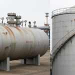
![Pressure vessel vs storage tank visual comparison industrial equipment]()
Pressure Vessels vs Storage Tanks Major Differences
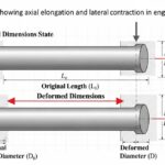
![“Poisson’s ratio showing axial elongation and lateral contraction in engineering material”]()
Poisson’s Ratio Explained With Formula, Examples and Engineering Significance
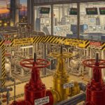
![Emergency Shutdown System layout in industrial plant with ESD valves and safety instrumentation]()
Emergency Shutdown System Design Working Components and Safety Logic
![Project kick-off meeting discussion in engineering project planning room]()
Project Kick-Off Meeting Meaning Purpose and Agenda Explained
![Surge relief valve protecting pipeline from pressure surge and water hammer]()
Surge Relief Valve Design Function Types and Selection Guide
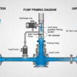
![Pump priming diagram showing air removal and liquid filling in centrifugal pump suction line]()
Pump Priming Explained with Methods and Industrial Applications