Table of Contents
What is Positive Material Identification and Why is it Critical?
In my 20-plus years of managing piping integrity on mega-scale petrochemical projects, I have seen how a single unverified component can compromise an entire facility. I remember a project where a supplier shipped what was documented as Grade 316 stainless steel piping. When we ran our quality checks, we discovered it was actually standard carbon steel that had been mislabeled at the mill. Had we installed those spools in our high-temperature acid service line, the piping would have suffered catastrophic corrosive failure within weeks of startup. This is where material verification becomes your ultimate line of defense.
Industrial plants operate under extreme pressures, temperatures, and corrosive environments. Relying solely on paper Material Test Reports (MTRs) is a risk no modern engineer should take. By utilizing advanced analytical tools directly in the field, we can verify the exact elemental makeup of our alloys in seconds, ensuring that what was designed is exactly what gets built.
Key Takeaways
- Verify alloy chemistry on-site without damaging the components.
- Ensure compliance with ASME Section II and API RP 578 standards.
- Prevent catastrophic failures caused by material mix-ups.
Understanding Positive Material Identification Testing Methods
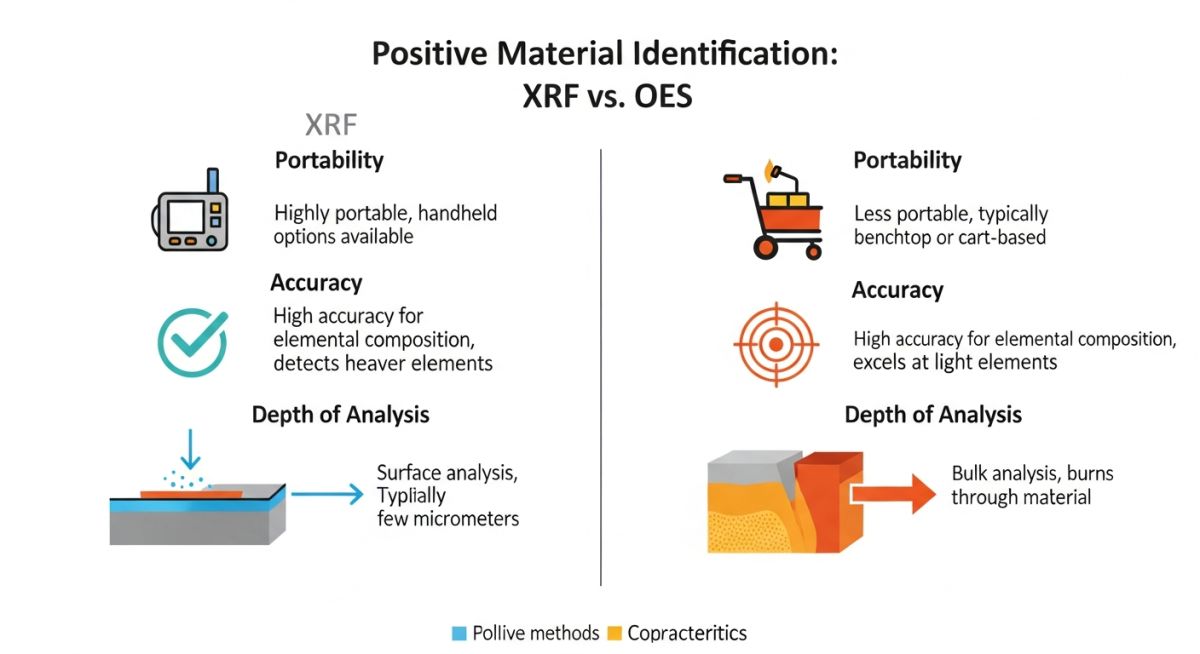
To implement a robust quality control program, you must understand the physics behind the tools we use. The two dominant technologies in the field are X-ray Fluorescence (XRF) and Optical Emission Spectroscopy (OES). Each has distinct operational parameters, limitations, and ideal use cases.
1. X-ray Fluorescence (XRF)
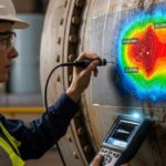
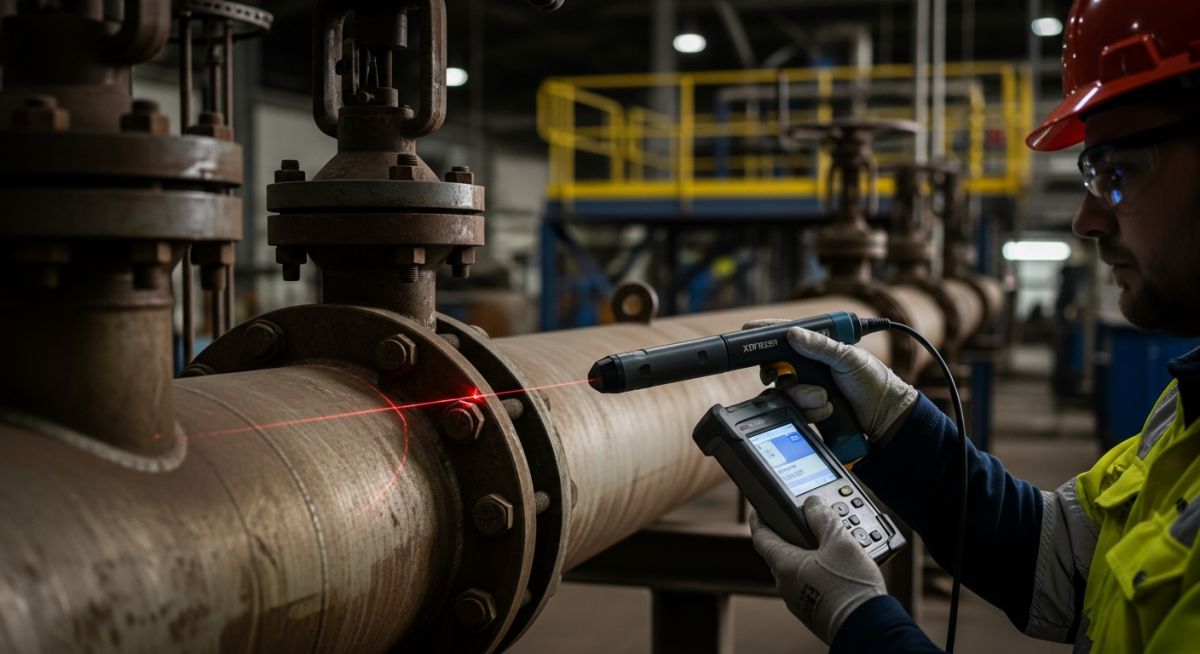
Handheld XRF analyzers are the workhorses of field testing. The device emits high-energy X-rays that strike the target material, displacing electrons from the inner shells of the atoms. As outer-shell electrons drop down to fill these vacancies, they release energy in the form of secondary (fluorescent) X-rays. Because each element emits a unique energy signature, the analyzer can identify and quantify the elements present.
While XRF is fast, non-destructive, and highly portable, it has physical limitations. Standard XRF units cannot reliably detect light elements with low atomic numbers, such as Carbon, Beryllium, or Lithium. This is a significant limitation when you need to distinguish between low-carbon and standard grades of stainless steel.
2. Optical Emission Spectroscopy (OES)
When carbon detection is mandatory, OES is the industry standard. This method uses an electric arc or spark to vaporize a tiny amount of the material’s surface, exciting the atoms into a high-energy state. As these excited atoms cool, they emit light across a spectrum of wavelengths. The instrument analyzes this light to determine the exact chemical composition, including carbon content.
OES is considered semi-destructive because it leaves a small, localized burn mark on the component surface. It also requires a high-purity argon gas supply to purge the optical path, making the equipment bulkier and more challenging to use on scaffolding or in tight spaces.
Calculating Carbon Equivalency for Weldability
In structural and piping steels, carbon content directly influences weldability and susceptibility to cracking. During field verification, we use the Carbon Equivalent (CE) formula to assess weldability. The formula is written as:
CE = Carbon + (Manganese / 6) + ((Chromium + Molybdenum + Vanadium) / 5) + ((Nickel + Copper) / 15)
If the calculated CE value exceeds 0.43 percent, preheating the material prior to welding is mandatory under ASME B31.3 guidelines to prevent hydrogen-induced cracking. This calculation highlights why accurate carbon detection via OES is so valuable on-site.
Positive Material Identification Standards and Limits
To ensure consistency across projects, we rely on established industry standards. The table below compares the operational capabilities of XRF and OES technologies to help you select the correct method for your specific alloy verification needs.
| Parameter | X-ray Fluorescence (XRF) | Optical Emission Spectroscopy (OES) |
|---|---|---|
| Portability | Excellent (Handheld, battery-powered) | Moderate (Requires cart, argon gas cylinder) |
| Carbon Detection | No (Except with specialized, high-end units) | Yes (Highly accurate down to low ppm levels) |
| Surface Damage | None (100% Non-destructive) | Minor (Leaves a small, localized burn mark) |
| Testing Speed | Fast (2 to 10 seconds per test) | Moderate (15 to 30 seconds per test) |
| Best Used For | High-alloy steels, Monel, Hastelloy, Titanium | Carbon steels, L-grade stainless steel verification |
When executing a quality plan, you must map your target alloys to their critical elements and applicable codes. The matrix below outlines the key verification targets for common industrial alloys.
| Alloy Grade | Nominal Composition | Critical Elements to Verify | Applicable Code | Recommended Method |
|---|---|---|---|---|
| 316/316L Stainless | Fe, Cr (16-18%), Ni (10-14%), Mo (2-3%), C (<0.03% for L) | Molybdenum, Carbon | ASME SA-312 | OES (for Carbon) / XRF (for Mo) |
| Duplex 2205 | Fe, Cr (22%), Ni (5%), Mo (3%), N (0.18%) | Chromium, Nickel, Molybdenum | ASME SA-790 | XRF |
| Monel 400 | Ni (63%), Cu (31%) | Nickel, Copper | ASME SB-165 | XRF |
| Chrome-Moly (P91) | Fe, Cr (9%), Mo (1%), V (0.2%) | Chromium, Molybdenum, Vanadium | ASME SA-335 | XRF |
How to Execute Field Material Verification
A successful material verification program depends on strict adherence to field procedures. Skipping steps leads to false readings, which can result in either rejecting good material or, worse, accepting incorrect alloys. Use this checklist to guide your field testing teams.
On-Site Verification Checklist
-
Instrument Calibration
Verify the analyzer using a certified reference standard block before starting each shift. Record the calibration log. -
Surface Preparation
Grind or sand the test area to remove paint, rust, scale, or decarburized layers. Ensure a minimum of 1 mm depth is cleared for OES testing. -
Environmental Controls
Ensure the test area is dry and shielded from high winds or extreme temperatures that can cause sensor drift. -
Measurement Duration
Maintain the analyzer contact for the full dwell time (typically 10 to 15 seconds) to ensure statistical accuracy. -
Documentation
Record the heat number, component tag, and serial number alongside the elemental percentage printout for full traceability.
Field Case Study: Real-World Application
The Problem: Unverified Piping in High-Temperature Service
During the construction of a high-pressure hydrocracker unit, the piping specification demanded 100% titanium-stabilized Grade 321 stainless steel to resist polythionic acid stress corrosion cracking. The supplier provided material test reports (MTRs) confirming compliance. However, during our random field audit, we suspected some piping spools looked slightly different in surface finish.
The Outcome: Rapid Detection and Replacement
We deployed a handheld XRF analyzer to test 100% of the installed piping spools. The scan revealed that 14 out of 110 piping elbows were actually standard Grade 304 stainless steel, completely lacking the titanium stabilization required by API RP 578. We immediately halted construction, cut out the non-compliant elbows, and replaced them with verified Grade 321 material. This proactive intervention prevented a catastrophic high-temperature hydrogen attack (HTHA) and saved the operator an estimated 4.2 million dollars in emergency shutdown costs.
This experience reinforced a fundamental rule in my engineering practice: trust, but verify. Paper certificates can be misplaced, mislabeled, or forged. Physical testing on-site is the only way to guarantee plant safety.
Frequently Asked Engineering Questions
What is the difference between XRF and OES in PMI testing?
Can handheld XRF detect carbon content in steel?
What percentage of materials should undergo PMI testing?
Does PMI testing damage the piping components?
How does API RP 578 govern PMI testing?
What should you do if a component fails PMI testing?
Complete Course on
Piping Engineering
Check Now
Key Features
- 125+ Hours Content
- 500+ Recorded Lectures
- 20+ Years Exp.
- Lifetime Access
Coverage
- Codes & Standards
- Layouts & Design
- Material Eng.
- Stress Analysis

📚 Recommended Resources: Positive Material Identification
Read these Guides


Related posts:
![An engineer performing an API 579 fitness for service assessment on an industrial pressure vessel.]()
How to Perform API 579 Fitness for Service Assessment
![3D CAD render of a bolted flange joint assembly showing a compressed gasket.]()
Understanding Gasket m and y Factors in Flange Design
![PASS/START-PROF 4.86 pipe stress analysis software interface displaying a 3D piping model.]()
PASS/START-PROF 4.86 Released: Discover the New Pipe Stress Analysis Capabilities
![ASME certification mark stamped on an industrial pressure vessel nameplate]()
What is ASME Certification? Procedure and Mark Explained
![Professional technician inserting a high-pressure hydro jetting nozzle into a sewer pipe cleanout.]()
What is Hydro Jetting and How Does It Work?
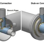
![Side-by-side comparison diagram of stub-in and stub-on piping branch connections.]()
Stub-in vs Stub-on Piping Connections: Engineering Design Guide