Table of Contents
Ultimate Guide to Plug Valves: Design, Working, and Industrial Applications
In my 20 years of managing piping systems in petrochemical plants, I have seen many valves fail under harsh conditions. When dealing with abrasive slurries, high-pressure gas, or corrosive chemicals, standard gate or globe valves often fall short. That is where plug valves come into play. These robust, quarter-turn mechanical devices offer a tight shut-off and reliable operation in the most demanding environments. Let me share my hands-on experience on how these valves operate, their key components, and how to select the right type for your piping network.
Key Takeaways
- Understand the quarter-turn mechanism that provides rapid isolation.
- Learn the differences between lubricated and non-lubricated designs.
- Identify the core components and standard symbols used in P&IDs.
- Discover how to calculate operating torque and pressure drops.
- Implement best practices for installation and maintenance.
Complete Course on
Piping Engineering
Check Now
Key Features
- 125+ Hours Content
- 500+ Recorded Lectures
- 20+ Years Exp.
- Lifetime Access
Coverage
- Codes & Standards
- Layouts & Design
- Material Eng.
- Stress Analysis
Understanding the Core Mechanics of Plug Valves
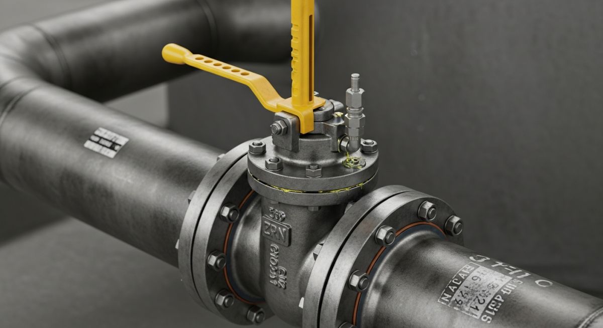
Plug Valve Mechanics: The operational mechanism relies on a rotating plug containing an internal port that aligns or misaligns with the flow path to achieve positive isolation in accordance with API 599 specifications.
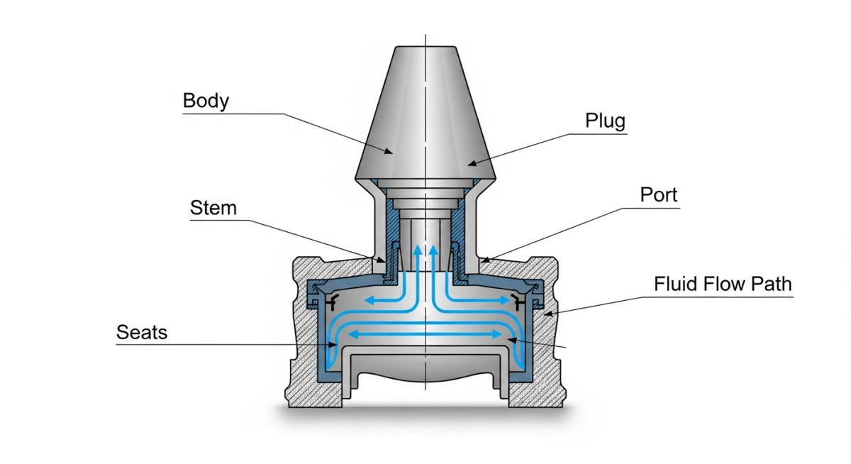
The design of a plug valve is elegant in its simplicity. The primary components include the valve body, the plug (which can be tapered or cylindrical), the stem, and the seating arrangement. The plug features a hollow passage, known as the port, through which the fluid flows. When you rotate the stem by 90 degrees, the plug turns, aligning the port with the pipeline to allow full flow, or positioning the solid face of the plug against the flow path to block it completely.
In my experience, the tapered plug design is the most common because the taper helps in wedging the plug into the body seat, creating a tighter seal. The contact area between the plug and the body is significantly larger than that of a ball valve, which makes plug valves highly effective for high-pressure applications but also results in higher operating torque.
Key Types of Plug Valves
Depending on the service conditions, we categorize these valves into several distinct types:
- Lubricated Plug Valves: These valves inject a specialized lubricant under pressure between the plug face and the body seat. The lubricant reduces operating torque, prevents corrosion, and acts as a secondary seal. They are ideal for abrasive services.
- Non-Lubricated Plug Valves: These utilize a sleeve or liner made of a resilient material like PTFE or elastomer fitted inside the body cavity. The sleeve reduces friction, eliminating the need for regular lubrication, making them excellent for chemical services where contamination must be avoided.
- Multi-port Plug Valves: These designs feature three or more ports, allowing the valve to divert, mix, or bypass flows. A single multi-port valve can often replace two or three straight-way valves, simplifying piping layouts.
- Eccentric Plug Valves: The plug is offset from the shaft centerline. This design ensures that the plug only contacts the seat at the final point of closure, minimizing wear and torque during operation.
Engineering Calculations and Torque Sizing
To size an actuator correctly, we must calculate the total operating torque. The formula is:
Where:
- T_seat: Seat friction torque, which is highly dependent on the differential pressure across the plug and the coefficient of friction of the seating material.
- T_packing: Packing friction torque, determined by the stem diameter and packing tightness.
- T_bearing: Stem bearing friction torque.
The flow coefficient (Cv) determines the pressure drop across the valve. For a fully open plug valve, the pressure drop is calculated using the formula:
Where Delta_P is the pressure drop, G is the specific gravity of the fluid, and Q is the flow rate. Because the port area of a plug valve is often smaller than the pipeline area (regular port design), the Cv is typically lower than that of a full-port ball valve, resulting in a slightly higher pressure drop.
For detailed design standards, engineers should refer to ASME B16.34 for pressure-temperature ratings and API 599 for metal plug valve designs.
Standard Specifications and Ratings of Plug Valves
Plug Valve Specifications: The dimensional limits, pressure-temperature ratings, and material selections are governed by ASME B16.34 and API 599 to ensure structural integrity under extreme operating conditions.
Selecting the correct valve requires comparing the performance characteristics of lubricated and non-lubricated designs. Below is a comprehensive engineering comparison table to guide your selection process.
| Parameter | Lubricated Plug Valves | Non-Lubricated Plug Valves |
|---|---|---|
| Lubrication Requirement | Regular injection of sealant required | No lubrication required (uses PTFE/elastomer sleeve) |
| Maintenance Frequency | High (preventative maintenance schedules) | Low (sleeve replacement during overhauls) |
| Temperature Limits | Up to 538°C (1000°F) with high-temp sealants | Limited by sleeve material (typically up to 204°C/400°F for PTFE) |
| Slurry Suitability | Excellent (sealant prevents particle ingress) | Moderate (abrasive particles can score the sleeve) |
| Seat Wear | Minimal due to continuous lubrication film | Gradual wear on the sleeve over time |
| Typical Applications | Crude oil, natural gas, mining slurries | Corrosive chemicals, acids, food processing |
To ensure compliance with international piping codes, engineers must map the physical parameters of the valve to the correct industry standards. The matrix below outlines these critical relationships.
| Technical Entity | Acronym / Standard | Physical Parameter | Hyperlinked Reference |
|---|---|---|---|
| Valve Design Standard | API 599 / ASME B16.34 | Wall thickness, pressure-temperature ratings | API Standards |
| Pressure Testing | API 598 | Shell and seat leakage rates | API 598 Testing |
| Face-to-Face Dimensions | ASME B16.10 | End-to-end installation length | ASME B16.10 |
| Material Selection | ASTM A216 WCB / LCC | Carbon steel body casting chemistry | ASTM Materials |
| Fire Test Standard | API 607 / API 6FA | Seat integrity during external fire exposure | API Fire Safety |
Site Verification Checklist for Valve Installation
Installation Quality Control: The pre-commissioning checklist ensures correct alignment, torque verification, and seal integrity of plug valves prior to system pressurization under ASME B31.3 guidelines.
Before installing any plug valve on-site, I always insist on a rigorous verification process. Improper installation can lead to premature seat wear, high operating torque, or catastrophic leakage. Use the checklist below to verify your installation.
Field Verification Steps
-
Verify that the valve flow direction arrow matches the actual process flow direction. -
Inspect the internal plug port and body cavity for any debris, weld slag, or rust. -
Check flange alignment and ensure the piping is not putting excessive bending stress on the valve body. -
For lubricated valves, verify that the grease fittings are accessible and the sealant chamber is fully charged. -
Perform a manual cycle test (open to close) to ensure smooth operation without binding. -
Verify that the actuator limit switches are correctly calibrated to prevent over-rotation. -
Ensure all flange bolts are torqued in a star pattern to the specified values in ASME PCC-1.
Field Case Study: Real-World Application
The Problem: Rapid Seat Erosion in Slurry Service
At a major mining facility in Western Australia, the primary tailings line experienced chronic failures. The abrasive slurry, containing 45% solids by weight, eroded the seats of standard gate valves within three weeks of installation. This caused severe internal leakage, pipeline downtime, and high maintenance costs.
The Solution: Retrofitting with Eccentric Plug Valves
We replaced the gate valves with eccentric non-lubricated plug valves featuring a heavy-duty polyurethane body lining and a nickel-plated plug. The eccentric design prevented plug-to-seat contact until the final degree of closure, reducing wear. The valves operated continuously for 24 months without a single failure, saving over 120,000 in maintenance and downtime.
My direct recommendation for any piping engineer dealing with high-solids slurries is to avoid gate or ball valves. Instead, specify eccentric plug valves with resilient linings to handle the abrasive nature of the fluid.
Frequently Asked Engineering Questions
Plug Valve FAQs: This technical reference addresses common field queries regarding plug valve selection, maintenance, and operational limits under API 599 standards.
What is the difference between a plug valve and a ball valve?
Why do plug valves require high operating torque?
Can plug valves be used for throttling applications?
How often should lubricated plug valves be greased?
What are the primary advantages of multi-port plug valves?
What causes a plug valve to seize, and how can it be prevented?

📚 Recommended Resources: Plug Valves
Read these Guides
🎓 Advanced Training


Related posts:
![Infographic flowchart of the GRP GRE FRP piping stress analysis workflow in START-PROF.]()
Rigid Struts: Definition, Applications, and Modeling in Caesar II
![3D stress analysis model of GRP piping system in START-PROF software showing stress distribution.]()
Stress Analysis of GRP / GRE / FRP Piping using START-PROF
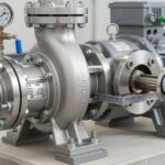
![Industrial centrifugal pump installed on a concrete foundation with precision piping and alignment.]()
How to Use a Pump Installation Checklist for Maximum Reliability
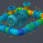
![3D Caesar II pipe stress analysis model of a centrifugal pump piping system showing stress distribution.]()
Pump-Piping Alignment Caesar II Stress Analysis Methodology
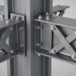
![3D render of a structural steel cross-bracing connection with a gusset plate.]()
Mastering Steel Connections with a Cross-Bracing Design Example
![Industrial engineer checking shaft alignment on a centrifugal pump during commissioning.]()
How to Use a Pump Commissioning Checklist for Start-Up