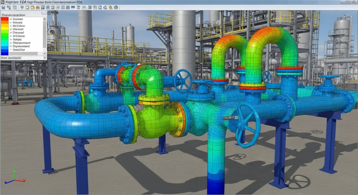
Piping Stress Analysis Specification: Flexibility and Compliance
In my two decades of managing high-pressure piping projects, I have observed that the most common cause of premature system failure is not poor material selection, but inadequate flexibility design. A robust Piping Stress Analysis Specification acts as the primary defense against thermal fatigue and nozzle overstress.
This guide outlines the technical rigor required to move beyond basic code compliance. We will examine how to translate theoretical stress limits into actionable site specifications that protect your rotating equipment and pressure vessels from excessive piping loads.
Key Takeaways for Engineers:
- Establishing clear displacement limits for sensitive equipment nozzles.
- Defining load cases for sustained, thermal, and occasional stress conditions.
- Standardizing software modeling inputs to ensure consistent design output.
- Implementing rigorous support selection criteria to manage thermal expansion.
Technical Deep-Dive: Piping Stress Analysis Specification
Piping Flexibility Design: The systematic evaluation of pipe geometry and support configurations to ensure that thermal expansion and contraction do not exceed allowable stress ranges defined by ASME B31.3.
When I draft a Piping Stress Analysis Specification, I focus on the interaction between the piping system and the connected equipment. The primary objective is to limit the forces and moments at equipment nozzles to values lower than the manufacturer’s allowable limits, often referencing API 610 for pumps or API 617 for compressors.
Defining Stress Categories
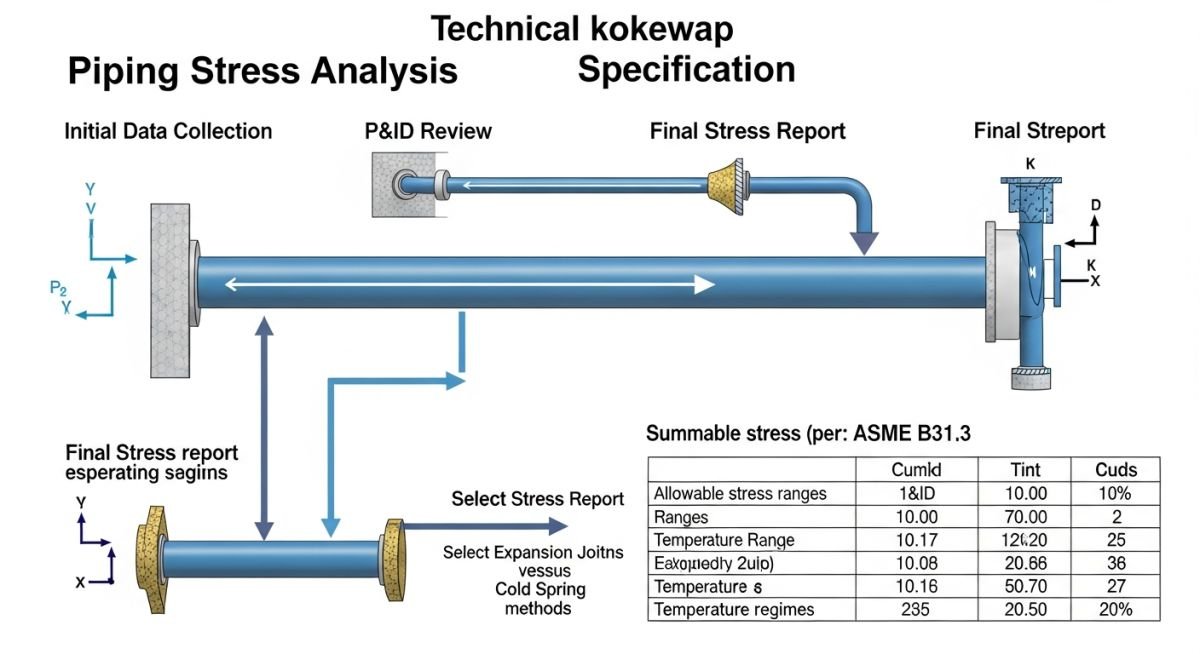
The specification must explicitly define the three primary load categories. Sustained loads (weight, pressure) must satisfy the longitudinal stress limit, calculated as the sum of pressure stress and bending stress due to weight. Thermal loads are evaluated based on the displacement stress range, which accounts for the full range of temperature cycles.
Field Warning: The “Cold Spring” Trap
Never rely on cold spring to reduce thermal loads in your specification unless you have a rigorous site verification process. In my experience, contractors rarely achieve the calculated cold spring percentage, leading to unexpected stress states during operation.
Flexibility and Expansion Control
Flexibility is achieved through geometry (loops, offsets) or mechanical components (expansion joints). The specification must mandate that expansion loops are sized based on the total thermal growth, calculated as delta L equals alpha times L times delta T. Where space is constrained, I specify the use of bellows or ball joints, provided they are supported by a detailed fatigue analysis.
For high-temperature lines, the specification must require a formal “Stress Isometric” review. This review ensures that the support types—specifically spring hangers—are correctly modeled to account for the vertical travel of the pipe during the transition from ambient to operating temperature.
Flexibility Specification Impact: The strategic implementation of rigorous stress analysis protocols balances the trade-off between system longevity and initial capital expenditure.
Advantages
- Extends equipment service life by minimizing nozzle loads.
- Prevents catastrophic fatigue failure in high-cycle systems.
- Optimizes support placement, reducing structural steel costs.
- Ensures compliance with international safety standards.
- Reduces maintenance downtime caused by flange leakage.
Disadvantages
- Increases initial engineering man-hours for complex models.
- Requires specialized software and highly skilled personnel.
- May necessitate additional space for expansion loops.
- Complex support designs can complicate field installation.
- Over-specification leads to unnecessary material weight.
Industrial Flexibility Applications: Tailoring stress analysis specifications to the unique thermal and pressure profiles of diverse process environments.
High-Pressure Steam Distribution
In power generation, steam lines operate at extreme temperatures where thermal expansion is the dominant design driver. My specifications here mandate rigorous spring hanger selection and the use of rigid anchors to direct expansion into designated loops, preventing turbine nozzle damage.
Cryogenic Liquefied Gas Processing
Cryogenic systems present the inverse challenge, where contraction during cool-down can pull supports off their seats. The specification must account for low-temperature material toughness and the specific contraction coefficients of stainless steel to prevent brittle fracture at weld joints.
Refinery Hydrocracker Units
Hydrocrackers involve high-pressure, high-temperature hydrogen service, requiring strict adherence to ASME B31.3. I focus on minimizing stress concentrations at branch connections and ensuring that the piping layout accommodates the significant thermal growth of large-bore reactor piping.
When developing a robust piping stress analysis specification, engineers must define clear boundary conditions and material property limits. These parameters ensure that the computational model accurately reflects the physical behavior of the piping system under operational and upset conditions, adhering strictly to ASME B31.3 requirements.
The following table outlines the critical input variables required for static and dynamic analysis. Proper documentation of these values prevents common modeling errors, such as incorrect thermal expansion coefficients or misidentified support stiffness, which often lead to premature system failure or excessive nozzle loading on rotating equipment.
| Parameter | Standard/Reference | Design Limit/Constraint |
|---|---|---|
| Thermal Expansion | ASME B31.3 | Calculated based on T-ambient to T-design |
| Pressure Thrust | ASME B31.3 | Internal pressure x cross-sectional area |
| Nozzle Loads | API 610 / API 617 | Must not exceed equipment manufacturer limits |
| Support Friction | MSS SP-58 | Coefficient of friction (0.3 to 0.4) |
Engineers should note that these values are baseline requirements. For high-temperature services or cryogenic applications, additional sensitivity analysis regarding material modulus degradation is mandatory to maintain structural integrity.
The integration of various engineering entities into a unified piping stress analysis specification requires a systematic approach to data management. By mapping physical components to their respective regulatory standards, we ensure that every element of the piping system—from valves to expansion joints—is accounted for in the flexibility analysis.
This matrix serves as a reference guide for junior and senior engineers to verify that all critical components are correctly categorized. It highlights the relationship between the physical hardware and the governing code, ensuring that the stress analysis software inputs are aligned with industry-standard safety factors and performance criteria.
| Entity | Standard | Primary Function |
|---|---|---|
| Expansion Loop | ASME B31.3 | Absorb thermal expansion via geometry |
| Spring Hanger | MSS SP-58 | Provide constant support during movement |
| Flange Joint | ASME B16.5 | Pressure containment and sealing |
Maintaining this matrix throughout the project lifecycle allows for rapid identification of non-compliant components during design reviews. It is a living document that should be updated whenever a change in piping material or routing occurs.
Before finalizing any piping stress analysis specification, a comprehensive site verification is required to bridge the gap between theoretical models and physical reality. My experience shows that discrepancies between the isometric drawings and the actual field installation are the leading cause of piping system failures.
-
[ ]
Support Alignment: Verify that all spring hangers are set to the correct cold load position as specified in the stress report. -
[ ]
Thermal Clearance: Confirm that no structural steel or secondary piping interferes with the calculated thermal expansion envelope. -
[ ]
Nozzle Loading: Check that equipment nozzles are free of external piping weight and that temporary supports have been removed. -
[ ]
Material Verification: Ensure the installed pipe wall thickness matches the design specification used in the ASME B31.3 analysis. -
[ ]
Expansion Joint Integrity: Inspect bellows for shipping bars that must be removed prior to system commissioning.
Each item on this checklist must be signed off by both the piping stress engineer and the site construction lead. Failure to verify these points can result in excessive stress concentrations that exceed the allowable stress range, leading to fatigue failure or flange leakage during the first thermal cycle.
The Problem: Excessive Nozzle Loading on Centrifugal Pump
A high-pressure process line experienced recurring flange leaks at the pump suction nozzle during startup, despite the initial stress analysis showing compliance.
- The actual piping installation deviated from the isometric by 150mm.
- The cold spring effect was not properly accounted for during the installation phase.
- Friction at the sliding supports was higher than the assumed coefficient of 0.3.
- Thermal growth of the pump casing was neglected in the original model.
The Outcome: Successful Remediation and System Stability
By re-modeling the system with the as-built dimensions and adjusting the support configuration, we achieved a stable operating state.
- Reduced nozzle loads by 40% through the addition of a spring-loaded support.
- Eliminated flange leakage by implementing a strict bolt-torque procedure.
- Validated the new model against field-measured displacements during the next heat-up cycle.
- Established a new site-wide standard for piping stress analysis specification documentation.
My recommendation is to always perform a “post-installation” stress check if the field routing deviates by more than 5% from the design isometric. This proactive step prevents costly downtime and ensures the long-term integrity of the piping system.
What is the primary purpose of a piping stress analysis specification?
- Establishing design temperature and pressure envelopes.
- Defining the criteria for flexibility analysis and thermal expansion control.
- Setting the requirements for support selection and nozzle load limitations.
- Standardizing the software inputs and reporting formats for consistency across projects.
How does ASME B31.3 define the allowable stress range?
- It accounts for both the hot and cold conditions of the piping system.
- The code provides specific factors for fatigue life based on the total number of cycles.
- Engineers must ensure that the displacement stress range does not exceed this calculated value to prevent fatigue failure.
When is a formal flexibility analysis required?
- Systems operating at high temperatures where thermal expansion is significant.
- Piping connected to sensitive rotating equipment like pumps or compressors.
- Systems with complex geometries, large diameters, or thin-walled pipe sections.
- Any system where the potential for vibration or dynamic loading exists.
What role does friction play in stress analysis?
- It can prevent the pipe from moving freely during thermal expansion, leading to higher localized stresses.
- Engineers must apply a realistic coefficient of friction, typically between 0.3 and 0.4 for steel-on-steel.
- Ignoring friction can lead to an underestimation of the loads transferred to equipment nozzles.
- In some cases, friction is beneficial for damping, but it must be carefully modeled to ensure safety.
How are nozzle loads managed in the specification?
- The specification must reference API 610 or API 617 for allowable loads.
- Piping must be designed to be self-supporting near the nozzle to minimize external forces.
- Spring hangers are often used to isolate the nozzle from thermal growth of the main header.
- Regular audits of the stress model are required to ensure that nozzle loads remain within the manufacturer’s specified limits.
Why is cold spring used in piping design?
- It reduces the reaction forces on equipment nozzles during the hot operating state.
- It is particularly useful in high-temperature systems where thermal expansion is extreme.
- The specification must clearly define the cold spring percentage and the installation procedure.
- Verification of the cold spring is essential during the construction phase to ensure the intended stress reduction is achieved.
📚 Recommended Resources: Piping Stress Analysis Specification
Read these Guides
🎓 Advanced Training


Complete Course on
Piping Engineering
Check Now
Key Features
- 125+ Hours Content
- 500+ Recorded Lectures
- 20+ Years Exp.
- Lifetime Access
Coverage
- Codes & Standards
- Layouts & Design
- Material Eng.
- Stress Analysis
