Piping Materials vs Pipeline Materials: Key Differences and Engineering Standards
In my 20+ years of piping engineering experience, I have seen many young engineers make the mistake of treating piping and pipelines as the same system. I remember a major refinery expansion project in 2014 where a junior engineer specified ASTM A106 Grade B piping for a long-distance cross-country water transport line, and conversely, tried to use API 5L X60 pipeline steel inside a high-temperature process unit. The resulting design review was a wake-up call for the entire team.
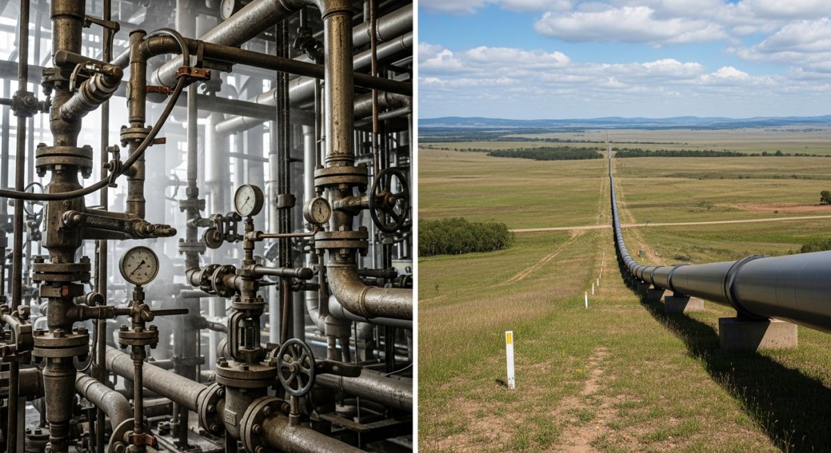
Understanding the boundary between process piping and cross-country pipelines is not just an academic exercise; it is a fundamental safety and cost requirement. Piping systems inside a plant boundary (ISBL) face high temperatures, cyclic thermal expansion, and highly corrosive chemical mixtures. Pipelines outside the plant boundary (OSBL) span miles of varying soil conditions, seismic zones, and environmental hazards, requiring high yield strength and ductility to withstand bending stresses.
Key Takeaways from an Expert’s Perspective
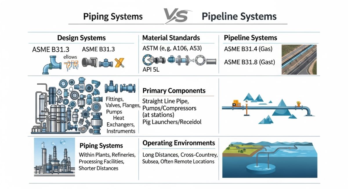
- Design Codes: Process piping relies on ASME B31.3, while pipelines are governed by ASME B31.4 (liquids) and ASME B31.8 (gas).
- Material Chemistry: Piping steels focus on high-temperature creep resistance and corrosion allowances, whereas pipeline steels prioritize high yield-to-tensile ratios and field weldability.
- Stress Calculations: Piping design is limited by allowable stress with high safety factors, while pipeline design utilizes Specified Minimum Yield Strength (SMYS) with location-based design factors.
Piping Materials vs Pipeline Materials: Core Technical Differences
When we design process piping inside a chemical plant or refinery, we deal with a dense network of pipes, valves, and fittings. The primary challenges are thermal expansion, vibration, and chemical attack. Consequently, piping materials like ASTM A106 (carbon steel), ASTM A335 (alloy steel for high temperatures), and ASTM A312 (stainless steel) are selected for their excellent mechanical properties across a wide temperature spectrum.
Pipelines, on the other hand, are long-distance conduits. They run through deserts, mountains, and oceans. The primary engineering challenge is managing the massive volume of steel required. To keep wall thickness and transportation costs low, pipeline engineers specify high-strength low-alloy (HSLA) steels under the API 5L specification (such as X52, X60, X65, and X70). These materials achieve high yield strengths through micro-alloying elements like niobium, vanadium, and titanium.
Wall Thickness Calculations: ASME B31.3 vs. ASME B31.4/B31.8
The difference in design philosophy is clearly visible in the wall thickness formulas. For process piping under ASME B31.3, the design thickness (t) is calculated using the following formula:
Where:
- P: Internal design gauge pressure
- D: Outside diameter of the pipe
- S: Allowable stress value for the material at design temperature
- E: Quality factor (weld joint or casting quality)
- W: Weld joint strength reduction factor
- Y: Coefficient based on material type and temperature
For liquid pipelines under ASME B31.4, we use Barlow’s Formula modified by a design factor:
Where:
- S: Specified Minimum Yield Strength (SMYS) of the pipe
- F: Design factor (typically 0.72 for liquid pipelines, but can be lower based on location)
- E: Weld joint factor
Notice the difference: ASME B31.3 uses an “allowable stress” (S) which already incorporates a safety factor of 3 to 1 against tensile strength. ASME B31.4 uses the actual yield strength (SMYS) and applies a design factor (F) to establish the safe operating limit. This allows pipeline designs to utilize the material’s strength more aggressively, resulting in thinner walls over long distances.
Comparing Piping Materials vs Pipeline Materials Specifications
To help you make informed decisions during the material selection phase, I have compiled the primary mechanical and physical differences between standard piping and pipeline materials.
| Parameter | Process Piping Materials | Pipeline Materials |
|---|---|---|
| Primary Standards | ASME B31.3, ASTM A106, ASTM A333, ASTM A312 | ASME B31.4, ASME B31.8, API 5L (PSL1 & PSL2) |
| Yield Strength Range | Low to Moderate (205 MPa to 240 MPa for carbon steel) | High to Very High (245 MPa to 555 MPa / X42 to X80) |
| Temperature Limits | Extremely wide (-196°C to over 650°C with alloys) | Narrow range (-29°C to 120°C due to coatings/soil) |
| Wall Thickness Range | Standard schedules (Sch 40, 80, 160, XXS) | Custom wall thicknesses optimized to the millimeter |
| Weldability Focus | Shop fabrication, complex geometries, socket/butt welds | High-speed field girth welding, low carbon equivalent (CE) |
| Corrosion Allowance | Typically 1.5 mm to 3.0 mm added to wall thickness | Minimal; relies on chemical inhibitors and external coatings |
Technical Mapping & Specifications Matrix
The following matrix maps the core technical entities, structural acronyms, and physical parameters to their governing standards.
| Entity / Acronym | Technical Definition | Governing Standard | Critical Design Parameter |
|---|---|---|---|
| SMYS | Specified Minimum Yield Strength | API 5L / ASTM | Determines the plastic deformation threshold |
| PSL1 vs PSL2 | Product Specification Level (1 = Standard, 2 = Strict) | API 5L | PSL2 mandates fracture toughness testing (Charpy V-Notch) |
| CE (Carbon Equiv.) | Formula to assess weldability and cracking risk | AWS D1.1 / API 5L | Must be kept below 0.43% for field welding without preheat |
| NACE MR0175 | Standard for materials in sour (H2S) service | ISO 15156 | Limits hardness to 22 HRC to prevent cracking |
Field Verification Checklist for Material Selection
During my site audits, I always emphasize that a paper trail is only as good as the physical steel on the ground. Below is the checklist I use to verify materials at the construction site before welding begins.
Material Verification Checkpoints
-
MTR Verification: Cross-reference the heat numbers stamped on the pipe body with the mill’s Material Test Reports (MTRs) for chemical composition and mechanical properties. -
Dimensional Inspection: Measure the outside diameter (OD) and wall thickness at multiple points using calibrated ultrasonic thickness gauges. -
Hardness Testing: For sour service materials, perform field hardness testing to ensure values do not exceed 22 HRC (250 HV) per NACE MR0175. -
Bevel Angle Check: Verify that the pipe end bevels match the welding procedure specification (WPS)—typically 37.5 degrees for standard butt joints. -
Visual Surface Inspection: Inspect the pipe surface for laminations, deep gouges, or mechanical damage that exceeds 10% of the nominal wall thickness. -
Color Coding: Ensure the site’s material segregation color-coding system is applied to prevent accidental mixing of carbon steel and alloy steel. -
Coating Integrity: For pipeline materials, perform holiday detection on external coatings (like FBE or 3LPE) to identify pinholes or damage before lowering-in.
Field Case Study: Real-World Application
The Problem: High-Yield Steel in High-Temperature Service
During a fast-tracked gas plant expansion, a subcontractor ran short of ASTM A106 Grade B seamless piping for a 12-inch medium-pressure steam line operating at 280°C (536°F). To avoid schedule penalties, they substituted surplus API 5L X60 PSL2 pipeline pipe left over from the feed line. The subcontractor assumed that because the X60 pipe had a higher yield strength (60,000 psi vs. 35,000 psi for A106), it was a superior and safer choice.
The Outcome: Engineering Intervention and Rectification
I discovered this substitution during a routine P&ID compliance walkdown. I immediately issued a stop-work notice. API 5L X60 is a thermo-mechanically treated steel. At 280°C, the material would not fail immediately, but its long-term creep resistance and tensile properties would degrade rapidly over time. Furthermore, the weld chemistry of the X60 pipe was not compatible with the standard welding electrodes specified for the high-temperature steam system, creating a high risk of hydrogen-induced cracking.
We ordered the immediate removal of the X60 pipe. The line was re-fabricated using the correct ASTM A106 Grade B piping. This intervention prevented a potential steam line rupture that could have caused severe injuries and plant downtime.
My Recommendation: Always maintain a strict boundary between piping classes and pipeline classes. Never allow material substitutions based solely on yield strength. High yield strength does not equal high-temperature performance.
Frequently Asked Engineering Questions
Can API 5L pipe be used for process piping under ASME B31.3?
Why do pipeline materials have lower carbon content than piping materials?
What is the difference between API 5L PSL1 and PSL2?
How does the design factor (F) change in pipeline design?
Why is ASTM A106 not typically used for cross-country pipelines?
How do corrosion mitigation strategies differ between the two systems?
===FAQ_BLOCK===
Complete Course on
Piping Engineering
Check Now
Key Features
- 125+ Hours Content
- 500+ Recorded Lectures
- 20+ Years Exp.
- Lifetime Access
Coverage
- Codes & Standards
- Layouts & Design
- Material Eng.
- Stress Analysis