Table of Contents
Piping Layout Engineer Interview Questions for Piping Design
In my 20 years of managing piping design teams across global petrochemical projects, I have sat on both sides of the interview table. I can tell you that generic answers do not impress senior technical panels. They want to hear about real-world design constraints, code compliance, and the physical realities of a construction site.
When evaluating a candidate, I look for their ability to balance thermal flexibility with structural support integrity. This article breaks down the exact technical concepts, calculations, and code references you must master to demonstrate your expertise as a senior piping layout engineer.
Key Takeaways You Will Master:
- The exact mathematical and code-based answers to high-frequency interview questions.
- How to apply ASME B31.3 and API 610 standards to real-world layout challenges.
- Practical methods for routing pump suction, column piping, and steam headers.
- A downloadable site verification checklist to use on your next project.
Mastering Piping Layout Engineer Interview Questions
Piping Design Optimization: The process of balancing thermal flexibility, structural support, and hydraulic efficiency while minimizing overall material costs. This methodology ensures that piping layouts conform to ASME B31.3 stress limits and API 610 nozzle load criteria.
To excel in a technical interview, you must demonstrate a deep understanding of how piping layouts interact with static and dynamic forces. Let us break down the core areas where interviewers focus their questions.
1. Thermal Flexibility and Stress Analysis
One of the most common questions I ask candidates is: “How do you determine if a piping system requires formal computer-aided stress analysis?”
According to ASME B31.3 Clause 319.2.1, formal analysis is not required if the system duplicates a successfully operating layout or if the piping is of uniform size, has no more than two anchors, and satisfies the simplified empirical formula:
Where:
- D = Nominal pipe size (inches)
- y = Resultant of total displacement to be absorbed by the piping system (inches)
- L = Developed length of piping between anchors (feet)
- U = Anchor distance (straight line between anchors, feet)
- K = 0.03 for carbon steel systems
Never rely solely on the simplified empirical formula for systems operating above 150 degrees Celsius, or for piping connected to strain-sensitive equipment like pumps, compressors, or turbines. Doing so risks catastrophic nozzle failure.
2. Pump Piping Layout (API 610 Compliance)
Interviewers love to ask about pump suction piping. The layout of the suction line is paramount to preventing cavitation and ensuring stable pump operation.
When routing pump suction piping, you must maintain a straight run of at least 5 to 10 times the pipe diameter between the pump suction nozzle and the first elbow. This ensures a uniform velocity profile as the fluid enters the impeller. If an elbow is placed directly at the suction nozzle, it creates an uneven flow distribution, leading to localized low-pressure zones, cavitation, and premature bearing failure.
3. Column Piping Layout Principles
Column piping requires careful spatial coordination. You must arrange the piping close to the column shell to minimize the structural load on the vessel clips and to allow for efficient platform design.
In my experience, the best approach is to group the piping according to its destination. Keep the hot lines that require thermal expansion loops together, and position the cold lines where they will not interfere with maintenance access to manholes, instruments, and relief valves.
Standard Piping Clearance and Spacing Guidelines
Piping Clearance Standards: The minimum physical distances required between adjacent pipes, structural steel, and grade levels to ensure safe maintenance access and prevent thermal clashing. These values are derived from standard industrial practices and OSHA safety regulations.
During an interview, you may be asked to specify standard clearances. The table below outlines the industry-standard minimum clearances that I enforce on all my projects.
| Piping Scenario | Minimum Clearance | Engineering Justification |
|---|---|---|
| Pipe bottom to Grade (inside sleeper way) | 300 mm (12 inches) | Allows for painting, inspection, and prevents corrosion from standing water. |
| Pipe bottom to Grade (over main roads) | 6000 mm (20 feet) | Ensures safe passage for heavy mobile cranes and emergency vehicles. |
| Between adjacent flanges (staggered) | 25 mm (1 inch) | Prevents bolt interference during maintenance and allows for insulation thickness. |
| Piping to structural steel column | 50 mm (2 inches) | Accommodates structural tolerances and minor lateral pipe movements. |
Technical Mapping & Specifications Matrix
This matrix maps critical piping entities to their governing codes and primary design parameters.
| Entity / Component | Governing Code | Primary Design Parameter | Key Layout Consideration |
|---|---|---|---|
| Process Piping Systems | ASME B31.3 | Allowable Stress (Sc, Sh) | Thermal expansion loops and anchor placement. |
| Centrifugal Pumps | API 610 / ISO 13709 | Nozzle Load Limits | Straight run on suction; use of eccentric reducers (flat side up). |
| Pressure Vessels | ASME Section VIII Div 1 | Nozzle Thermal Movements | Flexible piping connections to prevent vessel shell overstress. |
| Pipe Flanges | ASME B16.5 | Pressure-Temperature Rating | Bolt tensioning clearance and gasket accessibility. |
Piping Layout Design Review Checklist
Design Review Checklist: A structured verification protocol used by lead engineers to audit 3D models and isometric drawings before fabrication release. This quality gate ensures compliance with ASME B31.3, constructability, and operations accessibility.
Before any piping layout is finalized or sent for stress analysis, I require my team to run through this verification checklist. This prevents costly field modifications and rework.
Piping Layout Verification Points:
-
Pump Suction Reducers: Verify that eccentric reducers on horizontal pump suction lines are installed “flat side up” (FSU) to prevent air pockets and subsequent pump cavitation.
-
Control Valve Station Accessibility: Ensure control valves and bypass valves are located at grade or accessible platforms. The handwheels must be within 1.2 meters of the standing surface.
-
High Point Vents and Low Point Drains: Confirm that hydrostatic vents are provided at all high points and drains are provided at all low points for system hydrotesting and commissioning.
-
Thermal Expansion Clearance: Check that piping loops have sufficient clearance from structural steel to expand without physical contact.
-
Orifice Plate Run Requirements: Ensure straight run requirements (typically 15D upstream and 5D downstream) are met for all flow orifices to guarantee measurement accuracy.
Solving Complex Piping Layout Challenges
Piping Stress Resolution: The engineering process of modifying piping routing or support configurations to mitigate excessive nozzle loads on rotating equipment. This case study demonstrates how to resolve API 610 pump nozzle overload using thermal loops.
Field Case Study: Real-World Application
The Problem: API 610 Pump Nozzle Overload
During the commissioning phase of a refinery expansion project, a 10-inch high-temperature hydrocarbon line (operating at 280 degrees Celsius) was exerting forces on a centrifugal pump nozzle that exceeded the allowable limits specified by API 610 Table 5 by over 250%.
The original layout was too rigid, and the thermal expansion of the vertical run was pushing directly down onto the pump suction nozzle, risking casing distortion and shaft misalignment.
The Outcome: Rerouting and Flexible Support Integration
As the lead engineer, I halted the piping installation and remodeled the system in Caesar II. We introduced a 3D expansion loop with two 90-degree elbows to redirect the thermal growth away from the pump.
We also replaced the rigid base support near the pump nozzle with a variable spring hanger. This modification absorbed the vertical thermal expansion while still supporting the dead weight of the pipe and fluid. The final stress analysis showed nozzle loads reduced to 85% of the API 610 allowable limits, ensuring safe and reliable pump operation.
My direct recommendation for any layout engineer facing similar issues is to always look at the system holistically. Do not just add supports; sometimes, removing a rigid support or adding flexibility through routing is the most elegant and cost-effective solution.
Piping Layout Engineer Interview Questions Explained
Piping Interview Preparation: A targeted review of core piping design principles, stress analysis concepts, and code requirements for technical evaluations. This compilation addresses the most common technical queries encountered during senior-level engineering interviews.
1. Why do we use eccentric reducers flat side up (FSU) on pump suction lines?
2. What is the difference between a 150# and a 300# flange rating?
3. How do you locate the first guide support from an expansion joint?
4. What is the purpose of a drip leg in a steam piping system?
5. How do you distinguish between primary and secondary stresses?
6. What are the key layout considerations for a relief valve (PSV) discharge line?
===FAQ_BLOCK===

📚 Recommended Resources: Piping Layout Engineer Interview Questions
Read these Guides
- 📄 What is a Sideboom Pipelayer? The Engineering Guide to Heavy Lift Operations
- 📄 What is a 3D Point Cloud? Tools, Features & Engineering Applications (2026)
- 📄 What is Chromoly Steel? AISI 4130 Characteristics & Engineering Applications
- 📄 Refractory Lining: Engineering Guide to Materials, Selection & Design


Related posts:
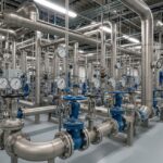
![Industrial metallic piping network with stainless steel pipes and valves in a processing plant.]()
What is Metallic Piping: Types, Advantages, Applications, and ASTM Standards
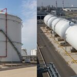
![Industrial gas processing facility comparing cryogenic LNG storage tanks and pressurized LPG bullet tanks.]()
What are the Differences Between LNG and LPG?
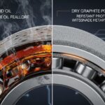
![Split-screen comparison of liquid oil failing under extreme heat versus dry graphite lubricating a mechanical bearing smoothly.]()
Why Is Graphite a Better Lubricant Than Oil in Industrial Piping?
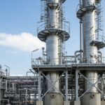
![Tall industrial distillation column tower at a chemical processing plant]()
What is a Distillation Column? Working Principles and Types
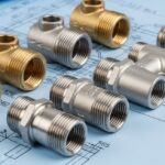
![Close-up of various metal pipe fittings with different thread types on an engineering blueprint.]()
Understanding the Different Types of Pipe Threads in Piping Systems
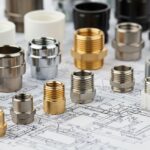
![A collection of different metal and plastic pipe ferrules resting on an engineering blueprint.]()
How Do Pipe Ferrules Ensure Leak-Free Industrial Piping Systems?