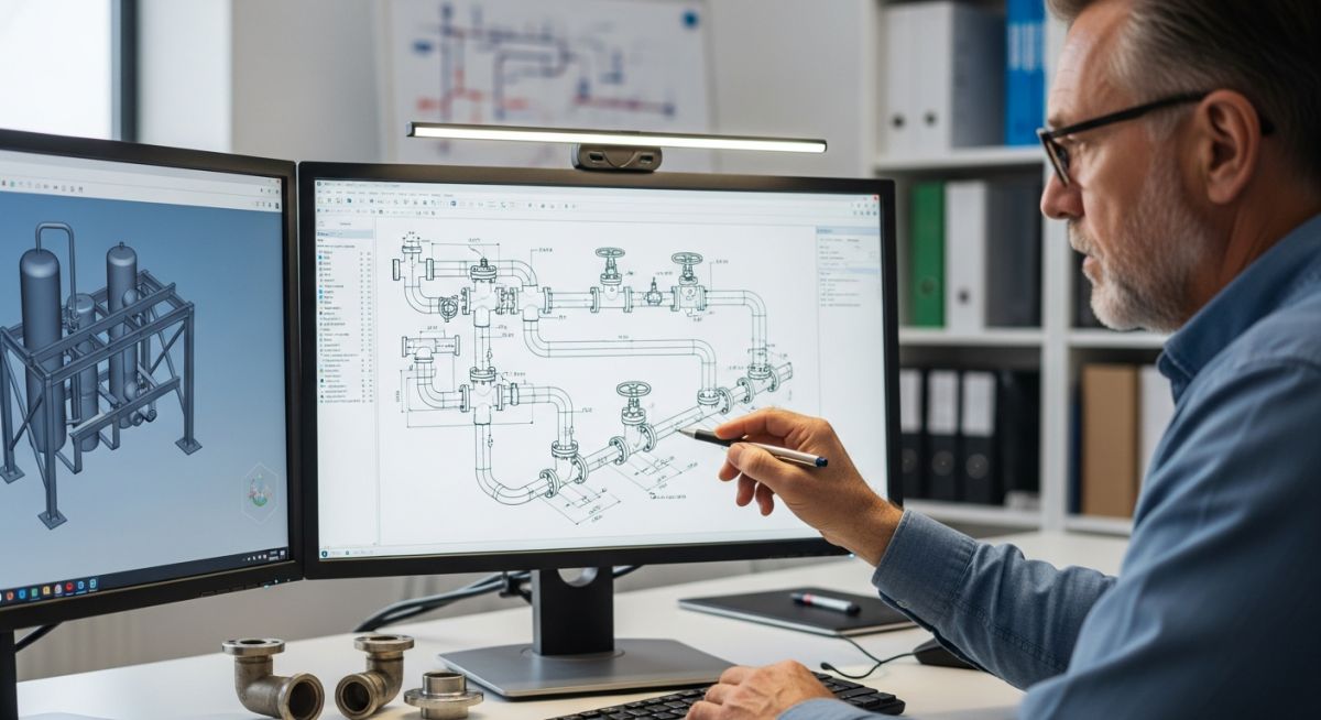
Piping Isometric Drawing Checklists: Ensuring Fabrication Precision
In my two decades of experience, I have seen far too many projects derailed by simple errors in isometric drawings. A single missing weld symbol or an incorrect flange rating can lead to thousands of dollars in rework and weeks of schedule slippage. Mastering Piping Isometric Drawing Checklists is not just about ticking boxes; it is about developing a rigorous mental model that catches discrepancies before they reach the shop floor.
When I review an isometric, I look beyond the lines. I verify the flow direction, the orientation of branch connections, and the compatibility of the Bill of Materials (BOM) with the project piping specifications. This guide provides the technical foundation you need to perform these checks with absolute confidence.
Key Takeaways for Quality Control:
- Validate all line numbers and piping class designations against the P&ID.
- Ensure every weld is mapped and assigned a unique identification number.
- Cross-reference the BOM with the latest approved vendor data sheets.
- Verify that all support locations are clearly dimensioned and tagged.
Technical Verification of Piping Isometric Drawing Checklists
Piping Isometric Drawing Checklists: A comprehensive technical audit process that ensures every isometric drawing adheres to project-specific design criteria and international pressure piping codes.
The core of any successful piping project lies in the accuracy of the isometric drawings. When I conduct a review, I follow a structured hierarchy of verification. First, I verify the geometric orientation. Is the North arrow consistent across all sheets? Are the elevations referenced to the correct plant datum? These seem like basic questions, but they are the most common sources of field installation errors.
Weld Mapping and Integrity
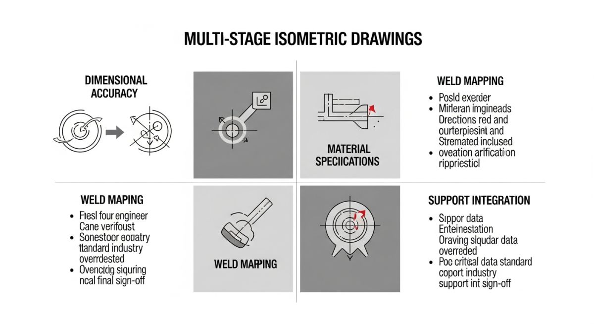
Weld mapping is the backbone of quality assurance. Every shop and field weld must be clearly identified. I ensure that the weld type (e.g., butt weld, socket weld, fillet weld) matches the piping class requirements defined in ASME B31.3. If a weld is located too close to a bend or a support, it creates a stress concentration point that could lead to premature fatigue failure.
Field Warning: Stress Concentration
Always verify that field welds are not placed within the heat-affected zone of a shop-fabricated bend. Per ASME B31.3, ensure that the minimum distance between welds is at least three times the pipe wall thickness or 25mm, whichever is greater, to prevent overlapping thermal stress zones.
Bill of Materials (BOM) Accuracy
The BOM is the primary document for procurement and fabrication. I perform a line-by-line check against the piping material specification (PMS). I look for discrepancies in flange ratings, gasket materials, and bolt lengths. A common error is the omission of special items like spectacle blinds or flow elements. I always check that the quantity of fittings matches the isometric layout, accounting for any potential waste or field-run adjustments.
Furthermore, I verify the pipe schedule. Using the wrong schedule can lead to catastrophic failure under high-pressure conditions. I calculate the required wall thickness using the formula: t = (P * D) / (2 * (S * E + P * Y)), where P is the design pressure, D is the outside diameter, S is the allowable stress, E is the quality factor, and Y is the temperature coefficient. If the specified schedule does not meet this minimum, the drawing must be rejected.
Isometric Quality Assurance: The strategic implementation of rigorous checking protocols to balance fabrication speed with long-term structural integrity.
Advantages
- Drastic reduction in field rework and site-based modifications.
- Improved material procurement accuracy through validated BOMs.
- Enhanced compliance with ASME B31.3 safety standards.
- Clearer communication between engineering, fabrication, and construction teams.
- Easier identification of potential stress concentration points before fabrication.
Disadvantages
- Increased initial engineering man-hours required for thorough reviews.
- Potential for “check-list fatigue” leading to missed subtle errors.
- Requires highly experienced personnel to identify non-obvious design flaws.
- Can create bottlenecks in the project schedule if not managed efficiently.
- Risk of over-engineering if the checklist is applied too rigidly.
Isometric Verification Applications: The deployment of standardized checking procedures across diverse industrial sectors to ensure operational safety and regulatory compliance.
High-Pressure Oil and Gas Pipelines
In high-pressure transmission lines, isometric checklists are vital for verifying that every weld meets the stringent non-destructive examination (NDE) requirements. By ensuring that weld maps are perfectly aligned with the isometric, we prevent the risk of catastrophic pipeline rupture under cyclic loading conditions.
Chemical Processing Plant Retrofits
When retrofitting existing chemical plants, space is often at a premium. Isometric checklists allow us to verify that new piping runs do not interfere with existing infrastructure, ensuring that all clearances are maintained according to safety standards and that maintenance access is preserved.
Cryogenic Liquefied Natural Gas (LNG) Facilities
In LNG facilities, material selection is critical due to extreme low-temperature service. Our isometric checklists focus heavily on verifying that the specified stainless steel grades and low-temperature gaskets are correctly identified in the BOM, preventing brittle fracture failures during startup and operation.
Power Generation Steam Systems
For high-temperature steam piping, the isometric review process includes verifying the correct installation of spring hangers and expansion loops. We ensure that the thermal expansion calculations are reflected in the isometric dimensions, preventing excessive stress on turbine nozzles and equipment connections.
When performing a rigorous review of piping isometric drawings, engineers must cross-reference physical design data against the project-specific Piping Material Specification (PMS) and the governing code, typically ASME B31.3. This table outlines the critical data points that must be verified during the pre-fabrication stage to prevent costly field rework and ensure structural integrity.
Each parameter listed below serves as a gatekeeper for quality control. Discrepancies in these fields often indicate a failure in the design-to-fabrication data transfer process, which can lead to incorrect material procurement or hazardous installation errors. Ensure that every isometric sheet is checked against the latest revision of the Piping and Instrumentation Diagram (P&ID) and the 3D model extract.
| Verification Category | Critical Data Point | Standard Reference |
|---|---|---|
| Dimensional Accuracy | Center-to-End (C-E) and Face-to-Face (F-F) | ASME B16.9 |
| Material Integrity | ASTM Material Grade & Schedule | ASTM A106/A312 |
| Weld Mapping | Weld ID, Type, and NDE Requirements | ASME BPVC Sec IX |
| Support Details | Pipe Shoe, Trunnion, and Anchor Locations | MSS SP-58 |
By maintaining this structured approach to data verification, the piping team minimizes the risk of field-fit issues. Always document the verification date and the reviewer’s initials on the drawing control log to maintain a clear audit trail for project quality assurance.
The following matrix maps the essential technical entities found within a standard isometric drawing package to their corresponding engineering standards and physical parameters. This mapping is vital for junior engineers and quality inspectors to understand the relationship between a drawing symbol and its real-world physical requirement.
Effective quality control relies on the ability to translate these entities into actionable fabrication instructions. When reviewing these components, focus on the interaction between the piping component and the surrounding structural environment, as defined by the project’s stress analysis report and the piping material class.
| Entity | Acronym | Standard |
|---|---|---|
| Flange Rating | ASME Class | ASME B16.5 |
| Valve Trim | API Trim | API 600 |
| Branch Connection | Weldolet/Tee | MSS SP-97 |
Use this matrix as a quick-reference guide during site audits. If a component on the isometric does not align with the specified standard in this matrix, it should be flagged immediately for engineering clarification before any cutting or welding occurs.
Verification of piping isometric drawings at the site level is the final line of defense against fabrication errors. This checklist is designed to ensure that the physical installation matches the design intent, accounting for field-run piping, support adjustments, and material availability.
- ☐ Verify that the isometric revision matches the latest P&ID and 3D model.
- ☐ Confirm all weld locations are accessible for NDE and post-weld heat treatment (PWHT).
- ☐ Check that the Bill of Materials (BOM) quantities match the physical spool requirements.
- ☐ Validate that all pipe supports are installed according to the support schedule and load requirements.
- ☐ Ensure that the orientation of valves and flow-directional components matches the process flow.
- ☐ Confirm that all branch connections are reinforced as per ASME B31.3 requirements.
Site supervisors must sign off on each item after physical inspection. If a deviation is found, it must be documented via a Field Change Request (FCR) and approved by the lead piping engineer before proceeding. This process ensures that the “as-built” documentation remains accurate for future maintenance and operational safety.
Problem: Misaligned Branch Connection in High-Pressure Line
- The isometric drawing failed to specify the exact orientation of a 2-inch branch connection on a 12-inch header.
- Fabricators installed the branch at a 45-degree angle instead of the required 90-degree vertical orientation.
- This misalignment caused a clash with an existing structural steel member, preventing the installation of the required pipe support.
- The error was only discovered during the final walk-through, leading to a significant schedule delay.
Outcome: Corrective Action and Process Improvement
- The branch was cut and re-welded with a full-penetration weld, followed by 100% radiographic testing (RT).
- A new isometric revision was issued to explicitly define the branch orientation using a coordinate-based reference.
- The project team implemented a mandatory “pre-fabrication review” meeting for all high-pressure piping spools.
- Total rework costs were mitigated by utilizing a localized repair procedure rather than replacing the entire header spool.
Recommendation: Always include clear orientation markers and coordinate references on all branch connections in isometric drawings. When in doubt, verify the physical space constraints with a 3D laser scan before finalizing the fabrication drawings.
Frequently Asked Engineering Questions
What is the primary purpose of a weld map in an isometric drawing?
- Each weld is assigned a unique identifier for traceability.
- The required NDE (Non-Destructive Examination) method is clearly linked to the specific weld.
- Welder qualifications are matched to the specific material and thickness of the joint as per ASME BPVC Section IX.
How do you handle discrepancies between the P&ID and the isometric?
- Issuing a formal Request for Information (RFI) to the design engineering team.
- Holding the fabrication of the affected spool until the RFI is resolved and the drawing is revised.
- Updating the P&ID to reflect the final design intent if the isometric is found to be the correct version.
Why is the Bill of Materials (BOM) critical for procurement?
- All components, including gaskets, bolts, and valves, are ordered to the correct specification.
- Material traceability is maintained from the manufacturer to the final installation.
- Waste is minimized by providing accurate cut lengths and quantities for pipe spools.
What are the requirements for branch connection reinforcement?
- The branch diameter exceeds a certain ratio relative to the header diameter.
- The operating pressure and temperature conditions exceed the inherent strength of the unreinforced opening.
- Calculations must be performed to ensure the area of reinforcement is sufficient to maintain the structural integrity of the header.
How do you verify pipe support locations on an isometric?
- Checking the support tag against the project support standard.
- Verifying that the support type (e.g., shoe, trunnion, anchor) is appropriate for the thermal expansion requirements.
- Ensuring that the support location does not interfere with weld access or other piping components.
What is the role of NDE in isometric drawing quality?
- Internal defects, such as porosity or lack of fusion, are identified before the system is pressurized.
- The weld meets the acceptance criteria defined by ASME B31.3.
- The documentation of NDE results provides a permanent record of the system’s safety and reliability for the life of the plant.
📚 Recommended Resources: Piping Isometric Drawing Checklists
Read these Guides
🎓 Advanced Training

Complete Course on
Piping Engineering
Check Now
Key Features
- 125+ Hours Content
- 500+ Recorded Lectures
- 20+ Years Exp.
- Lifetime Access
Coverage
- Codes & Standards
- Layouts & Design
- Material Eng.
- Stress Analysis
