Table of Contents
Piping Insulation: Functions, Materials, and Types of Pipe Insulation
In my 20-plus years of designing and commissioning piping systems for petrochemical plants, I have seen many engineers treat insulation as an afterthought. They focus heavily on pipe stress analysis, valve selection, and metallurgy, only to copy-paste a generic insulation specification at the very end. This is a recipe for operational disaster.
Properly engineered thermal barriers are fundamental to process stability. Whether you are managing a cryogenic LNG line at minus 160 degrees Celsius or a superheated steam line at 550 degrees Celsius, the choice of material, thickness, and cladding determines whether your plant runs efficiently or suffers from catastrophic energy loss and Corrosion Under Insulation (CUI). Let us dive deep into the practical mechanics of selecting and designing these systems.
Key Engineering Takeaways
- Understand the distinct thermal profiles of hot, cold, and acoustic insulation systems.
- Master the physical properties of calcium silicate, mineral wool, and cellular glass.
- Learn how to calculate economic thickness to balance capital expenditure against operational energy savings.
- Identify the root causes of Corrosion Under Insulation (CUI) and how to design mitigation strategies.
- Implement rigorous field inspection protocols to verify vapor barriers and cladding integrity.
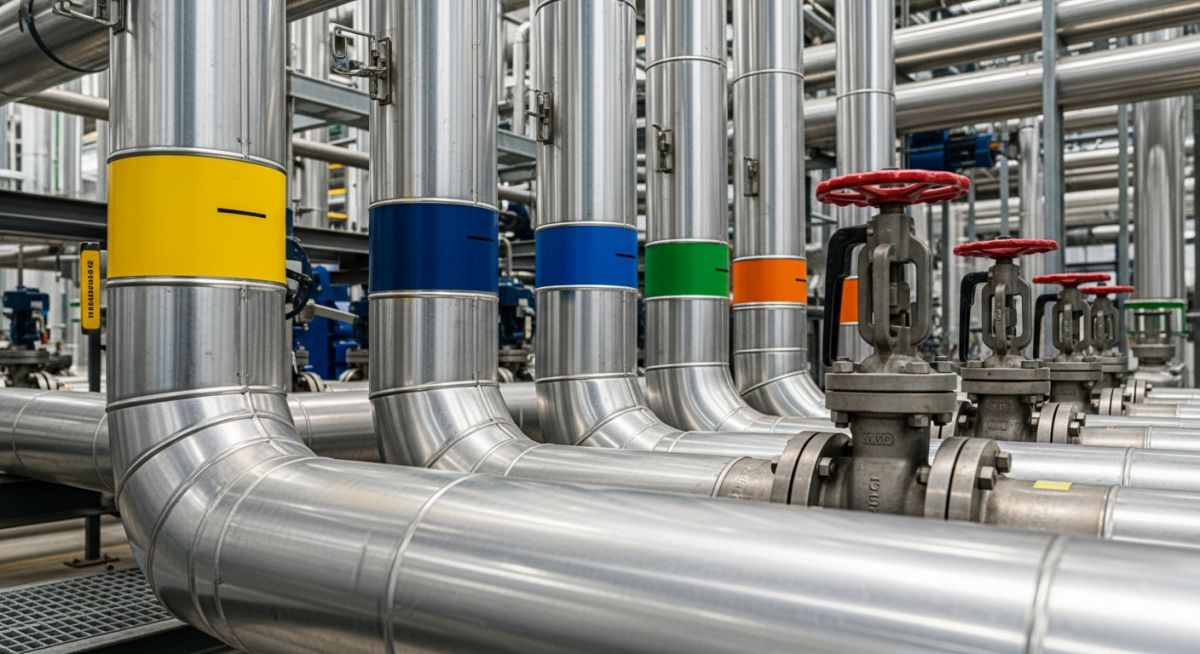
Why Is Piping Insulation Critical in Process Plants?
Thermal Energy Conservation: The systematic reduction of heat loss or gain in process piping to minimize utility costs and maintain precise fluid temperatures. This practice ensures compliance with energy conservation codes such as ASHRAE 90.1 and ISO 12241.
To design an effective system, we must first look at the underlying physics of heat transfer. For a cylindrical pipe, heat loss is not a simple linear equation. It is governed by radial heat conduction through the insulation material combined with convection and radiation from the outer cladding surface to the ambient air.
The fundamental formula for steady-state radial heat transfer through a single layer of cylindrical insulation is expressed as:
Where:
q = Heat loss rate (Watts)
k = Mean thermal conductivity of the insulation material (W/m·K)
L = Length of the pipe (meters)
Ti = Temperature at the inner insulation interface (Kelvin)
To = Temperature at the outer insulation interface (Kelvin)
Ri = Inner radius of the insulation layer (meters)
Ro = Outer radius of the insulation layer (meters)
In my practice, I use this equation to determine the “critical radius of insulation.” If the outer radius of your insulation is less than the ratio of thermal conductivity to the external heat transfer coefficient (k/h), adding insulation will actually *increase* heat loss rather than decrease it. This is a common pitfall on very small diameter lines (under 1/2 inch) carrying hot fluids.
Personnel Protection and Condensation Control
Beyond energy conservation, we design insulation for two safety-critical reasons: personnel protection and condensation prevention. According to ASTM C1055, the maximum safe touch temperature for metallic cladding in an industrial environment is 60°C (140°F) for a contact time of 5 seconds. If your process fluid exceeds this, you must insulate.
For cold and cryogenic lines, the goal is to keep the outer cladding temperature above the ambient dew point. If moisture condenses on the cladding, it will eventually find a path through the joints, saturate the insulation, and cause severe CUI or ice formation that can physically destroy the piping supports.
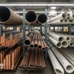
What Are the Primary Piping Insulation Materials?
Insulation Material Selection: The engineering process of matching physical properties like thermal conductivity, temperature limits, and compressive strength to specific operating environments. This selection aligns with ASTM standards to guarantee long-term mechanical performance.
Selecting the right material requires balancing thermal performance, mechanical durability, chemical compatibility, and fire resistance. The table below outlines the primary materials I specify in industrial projects.
| Material Type | Temp Range (°C) | Thermal Cond. (W/m·K at 100°C) | Compressive Strength | Primary Applications |
|---|---|---|---|---|
| Calcium Silicate | Up to 650°C | 0.059 | High (>150 psi) | High-temperature steam, refinery process lines, areas prone to foot traffic. |
| Mineral Wool | Up to 650°C | 0.045 | Low to Medium | Power plant piping, acoustic attenuation, high-temperature exhaust. |
| Cellular Glass | -268°C to 482°C | 0.052 | High (>100 psi) | Cryogenic LNG, cold chemical lines, underground/buried piping. |
| Polyisocyanurate (PIR) | -183°C to 149°C | 0.024 | Medium | Chilled water, low-temperature hydrocarbon processing. |
| Elastomeric Foam | -50°C to 105°C | 0.038 | Low (Flexible) | HVAC systems, refrigeration lines, condensation control. |
Technical Mapping & Specifications Matrix
To ensure compliance with international standards, we must map these materials to their respective ASTM specifications and design codes. This matrix serves as a quick reference for your design basis documents.
| Material Standard | ASTM Code | Water Absorption (%) | Combustibility | Recommended Cladding |
|---|---|---|---|---|
| Calcium Silicate Blocks | ASTM C533 | High (Requires barrier) | Non-combustible | 0.5mm Aluminum or SS304 |
| Mineral Wool Fiber | ASTM C547 | Medium (Hydrophobic grades) | Non-combustible | 0.5mm Aluminum or SS316 |
| Cellular Glass Blocks | ASTM C552 | 0% (Impermeable) | Non-combustible | SS316 (Corrosive environments) |
| Flexible Elastomeric | ASTM C534 | <0.2% | Self-extinguishing | UV-resistant PVC or mastic |
How to Verify Piping Insulation Quality On-Site?
Quality Assurance Inspections: The field verification protocols used to confirm that insulation thickness, cladding integrity, and vapor barriers meet engineering specifications. These inspections prevent moisture ingress and ensure compliance with CINI and NACE standards.
During my site walks, I frequently catch installation errors that compromise the entire thermal system. A single unsealed joint in a cold line cladding can ruin hundreds of meters of insulation within a year. Use this checklist to audit your installations before signing off on mechanical completion.
Field Inspection Checklist
-
Pre-Insulation Surface Prep: Verify that the pipe surface has been cleaned, primed, and coated in accordance with NACE SP0198 to prevent CUI. No insulation should be applied over wet or rusty pipes.
-
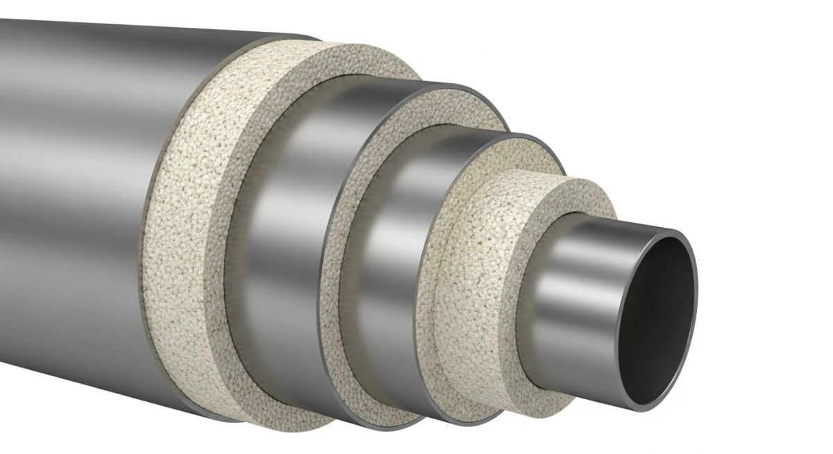
Staggered Joints: Ensure that multi-layer insulation systems have staggered longitudinal and circumferential joints to prevent direct thermal paths.
-
Vapor Barrier Continuity: On cold lines, inspect the vapor barrier membrane (mastic or foil) for punctures. It must be 100% continuous, especially around pipe supports and instrument taps.
-
Cladding Lap Direction: Verify that metal cladding laps are arranged in a “shed-water” configuration (shingle effect). Horizontal runs must lap downward, and vertical runs must lap away from the prevailing wind.
-
Expansion Joints: Confirm that expansion joints are installed in the insulation cladding on long, hot piping runs to accommodate thermal growth without buckling the metal jacket.
Field Case Study: Real-World Application
The Problem: Severe CUI and Steam Line Heat Loss
At a coastal petrochemical facility, a 12-inch medium-pressure steam line operating at 280°C was experiencing severe thermal degradation. The original insulation system consisted of mineral wool with aluminum cladding.
Over five years of operation in a humid, marine environment, water penetrated the cladding joints. The mineral wool acted like a sponge, holding moisture against the carbon steel pipe. This led to severe Corrosion Under Insulation (CUI), reducing the pipe wall thickness by 35% in critical areas and causing massive heat loss that destabilized downstream processes.
The Solution: System Redesign and Material Upgrade
I was brought in to redesign the system. We stripped the damaged mineral wool and grit-blasted the pipe to bare metal. We then applied a high-temperature Thermal Spray Aluminum (TSA) coating to the pipe wall to act as a sacrificial barrier against corrosion.
Instead of mineral wool, we specified a dual-layer system: an inner layer of calcium silicate (for high compressive strength and thermal resistance) and an outer layer of hydrophobic aerogel blanket. We replaced the aluminum cladding with 0.5mm thick 316 Stainless Steel cladding, secured with heavy-duty bands and sealed with high-temperature silicone sealant at all joints.
The Outcome
The redesigned system reduced external surface temperatures from an unsafe 85°C down to a stable 48°C, well within the personnel protection limits of ASTM C1055. Thermal imaging confirmed that heat loss was cut by 22%, saving the plant approximately 45,000 annually in fuel costs per kilometer of piping. Most importantly, subsequent non-destructive testing (NDT) inspections showed zero moisture ingress, completely halting the CUI mechanism.
Frequently Asked Engineering Questions
What is the difference between hot and cold piping insulation?
How does Corrosion Under Insulation (CUI) occur, and how can it be prevented?
What is the significance of the “economic thickness” of insulation?
Why is cellular glass preferred for cryogenic piping systems?
How do ASTM standards govern the selection of piping insulation?
What role does the vapor barrier play in cold insulation systems?
===FAQ_BLOCK===
Complete Course on
Piping Engineering
Check Now
Key Features
- 125+ Hours Content
- 500+ Recorded Lectures
- 20+ Years Exp.
- Lifetime Access
Coverage
- Codes & Standards
- Layouts & Design
- Material Eng.
- Stress Analysis

📚 Recommended Resources: piping insulation
Read these Guides
🎓 Advanced Training


Related posts:
![Super duplex stainless steel piping network on an offshore oil drilling platform.]()
Super Duplex Stainless Steel Oil and Gas Piping Design Guide
![Industrial duplex stainless steel piping system in a chemical processing facility.]()
Understanding Duplex Stainless Steel Properties and Industrial Piping Applications
![A welder performing a critical golden joint weld on an industrial steel pipeline.]()
What is a Golden Joint in Piping Systems?
![A collection of different types of industrial pipes classified by material and size on a storage rack.]()
Comprehensive Guide to Types of Pipes and Industrial Classification Systems
![Industrial piping network with digital overlays representing inch-dia and inch-meter engineering calculations.]()
What are Inch-Dia and Inch-Meter in Piping Systems?
![3D finite element stress analysis model of an industrial piping system showing stress distribution.]()
What Causes Piping System Stresses in Industrial Plants?