Table of Contents
Understanding the Fundamentals of Composite Piping System Design
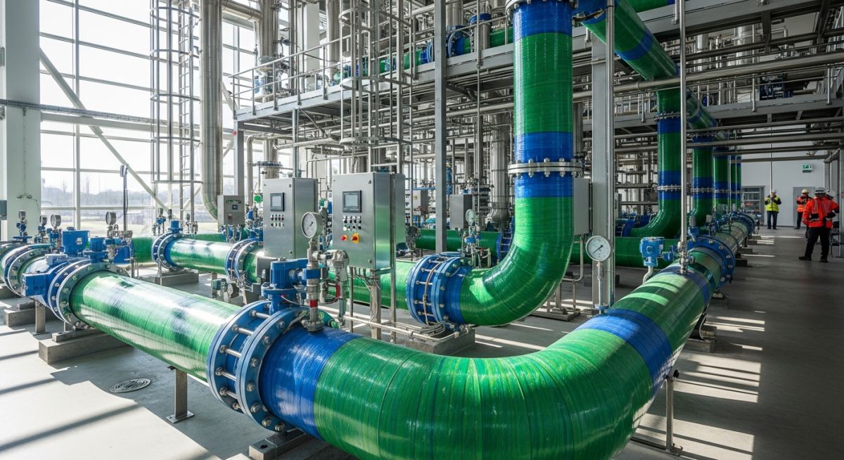
During my 20 years in the piping engineering field, I have watched traditional carbon steel and exotic alloy systems fail prematurely in highly corrosive environments. Whether dealing with aggressive seawater intake lines, chemical process plants, or offshore produced-water systems, metallic piping often demands expensive cathodic protection or frequent replacement. This is where a modern composite piping system changes the game. By combining high-strength glass or carbon fibers with chemically inert thermosetting resins, these systems deliver structural integrity that rivals steel while remaining completely immune to electrochemical corrosion.
In my experience, designing with composites requires a fundamental shift in mindset. You cannot simply swap steel for composite using the same support spans, thermal expansion loops, or jointing techniques. Composites are anisotropic materials; their mechanical properties depend heavily on the fiber orientation and manufacturing process. Understanding these nuances is what separates a trouble-free, 30-year installation from a catastrophic field failure.
Key Engineering Takeaways
- Corrosion Immunity: Complete resistance to galvanic, pitting, and microbiological corrosion without external coatings.
- Weight Reduction: Up to 75% lighter than equivalent steel piping, drastically reducing structural support requirements.
- Anisotropic Behavior: Mechanical properties vary by direction, requiring specialized stress analysis under ASME B31.3 Chapter VII.
- Lower Thermal Conductivity: Minimizes heat loss and often eliminates the need for external thermal insulation.
Why Choose a Composite Piping System for Corrosive Industrial Applications
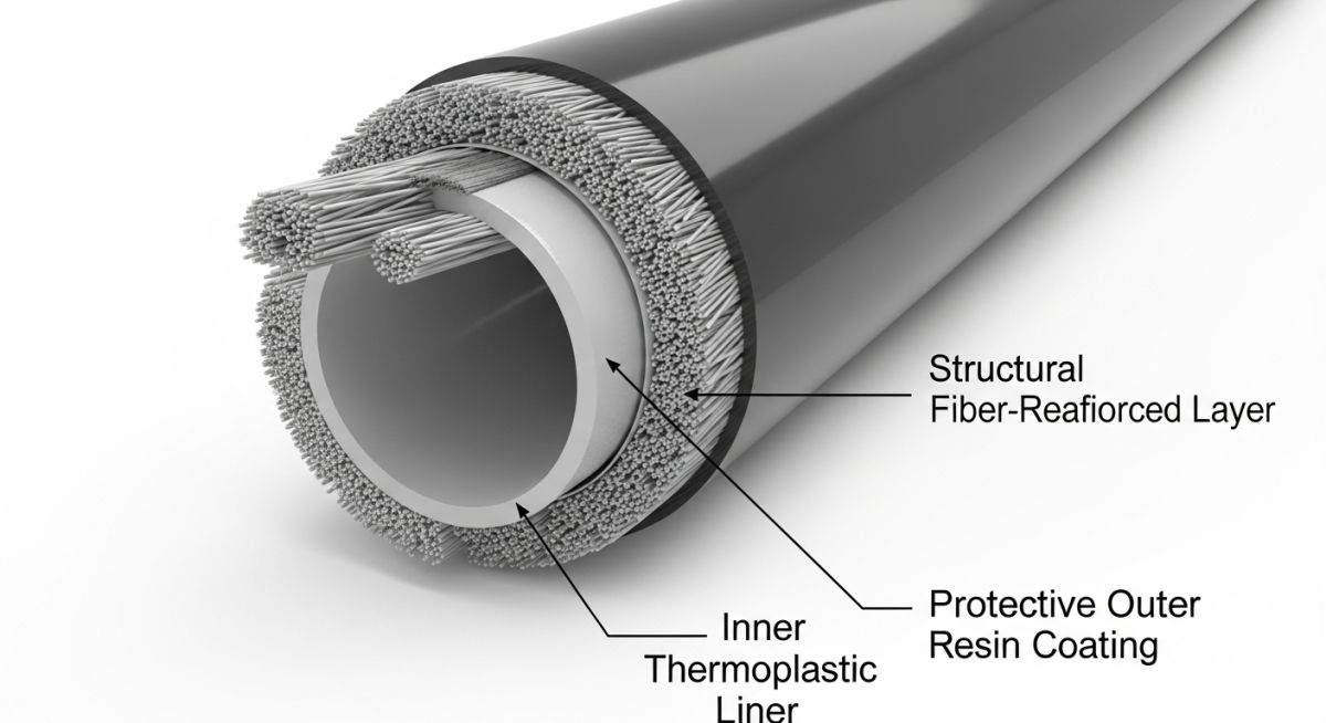
To design a reliable composite piping system, we must first dissect its structural anatomy. Unlike homogeneous metals, a composite pipe is built in distinct layers, each serving a specific mechanical or chemical purpose. The three primary layers are:
- The Inner Liner (Chemical Barrier): This is a resin-rich layer, typically 0.5 to 2.5 mm thick, reinforced with a synthetic veil. Its sole purpose is to resist chemical attack and prevent the process fluid from penetrating the structural layer.
- The Structural Layer: The powerhouse of the pipe. It consists of continuous glass or carbon filaments wound at precise angles (typically around 54 to 55 degrees relative to the pipe axis) embedded in a cured thermosetting resin matrix. This layer handles all internal pressure, bending moments, and external loads.
- The Outer Liner (External Barrier): A resin-rich outer layer designed to protect the structural fibers from environmental hazards, ultraviolet (UV) radiation, and mechanical impact during handling and installation.
Hoop Stress and Wall Thickness Calculations
In my practice, calculating the minimum structural wall thickness is the first step in verifying system integrity. Under ASME B31.3 Chapter VII and ISO 14692, the hoop stress must be carefully balanced against the design pressure.
S_h = (P * D_o) / (2 * t_min)
Where:
- S_h: Hoop stress acting on the structural wall (MPa)
- P: Internal design pressure (MPa)
- D_o: Outside diameter of the structural layer (mm)
- t_min: Minimum structural wall thickness (mm), excluding the inner liner thickness
Because the glass fibers are wound at a specific angle, the longitudinal strength is typically half of the hoop strength. This directional strength profile means that thermal expansion and water hammer forces can cause high axial stresses that must be carefully managed with anchors and guides.
Thermosetting Resin Selection
The choice of resin matrix dictates the temperature and chemical limits of your composite piping system. The three most common resins used in industrial applications are:
- Epoxy (GRE): Excellent mechanical properties and high temperature resistance (up to 110 degrees Celsius). Widely used in offshore oil and gas and high-pressure lines.
- Vinyl Ester (GRV): Superior resistance to highly acidic environments and oxidizing agents. Ideal for chemical processing plants.
- Polyester (GRP): The most economical option, suitable for water transport, municipal sewage, and low-pressure utility lines.
To highlight the stark differences between metallic and composite materials, the table below compares the physical and mechanical properties of carbon steel against common composite piping systems.
| Property | Carbon Steel (A106 Gr. B) | GRE (Epoxy) | GRV (Vinyl Ester) | GRP (Polyester) |
|---|---|---|---|---|
| Density (g/cm³) | 7.85 | 1.80 – 2.00 | 1.70 – 1.90 | 1.60 – 1.80 |
| Tensile Strength (MPa) | 415 | 200 – 350 | 150 – 250 | 80 – 150 |
| Elastic Modulus (GPa) | 200 | 15 – 25 | 10 – 18 | 8 – 15 |
| Thermal Expansion (10⁻⁶/°C) | 12 | 18 – 22 | 20 – 25 | 25 – 30 |
| Thermal Conductivity (W/m·K) | 50 | 0.30 – 0.40 | 0.25 – 0.35 | 0.20 – 0.30 |
Navigating the standards for composite piping can be challenging. This matrix maps the core technical entities, design codes, and typical industrial applications.
| Material Class | Primary Standards | Common Joint Types | Typical Applications |
|---|---|---|---|
| GRE (Glass Reinforced Epoxy) | ISO 14692, API 15HR | Adhesive Bonded, Threaded, Flanged | Offshore produced water, firewater loops, high-pressure hydrocarbons |
| GRV (Glass Reinforced Vinyl Ester) | ASME B31.3, ASTM D2996 | Lamination (Butt & Strap), Bell & Spigot | Acidic chemical lines, chlorine plants, industrial waste streams |
| GRP (Glass Reinforced Polyester) | AWWA C950, EN 1796 | Double Bell Coupler, Butt & Strap | Municipal water mains, cooling water lines, desalination intakes |
Key Design Standards for a Composite Piping System Installation
In my experience, more than 80% of composite piping failures occur at the joints due to poor field workmanship. Unlike steel welding, which is highly regulated and easily radiographed, composite jointing (especially adhesive bonding and hand lamination) is highly operator-dependent. The checklist below outlines the critical verification steps required during field installation.
Site Verification Checklist
-
Laminator Certification: Verify that all bonders and laminators hold valid certifications matching the specific pipe manufacturer and jointing method under ISO 14692 or ASME B31.3.
-
Environmental Controls: Ensure adhesive bonding is performed within the manufacturer’s specified temperature and humidity limits. Never bond joints in wet or dusty conditions.
-
Support Span Verification: Confirm that support spans match the composite design. Because composites have a lower elastic modulus, support spans are significantly shorter than those for steel.
-
Flange Bolt Torqueing: Use a calibrated torque wrench and follow a star pattern. Composite flanges are easily cracked by over-torqueing or misalignment. Always use flat-face gaskets.
-
Hydrostatic Testing: Ensure the system is slowly filled and vented. Test pressure must not exceed 1.5 times the system design pressure, and pressure hold times must comply with ISO 14692.
Field Case Study: Real-World Application
The Problem: Seawater Intake Line Failure
At a major coastal desalination facility, the original Super Duplex Stainless Steel (SDSS) seawater intake lines suffered severe localized crevice corrosion and pitting within 18 months of commissioning. The high chloride content of the warm seawater, combined with stagnant flow conditions during maintenance shutdowns, compromised the passive oxide layer of the alloy.
The replacement cost for SDSS was economically unviable, and the plant faced severe operational penalties due to unscheduled downtime.
The Outcome: Transition to GRE Composite Piping
I was brought in to oversee the engineering transition to a Glass Reinforced Epoxy (GRE) composite piping system designed to ISO 14692 standards. By replacing the metallic lines with GRE, we completely eliminated the corrosion mechanism.
The lightweight nature of the GRE pipes allowed us to reuse the existing pipe racks without structural modifications, saving millions in structural reinforcement. Over the past 8 years of continuous operation, the GRE lines have required zero maintenance, suffered zero corrosion, and reduced the total cost of ownership by over 60%.
My direct recommendation for any engineer dealing with high-chloride fluids or aggressive chemical services is to evaluate composite alternatives during the Front-End Engineering Design (FEED) phase. Designing for composites early avoids the costly rework of support structures and ensures optimal routing.
Frequently Asked Engineering Questions
What is the maximum temperature limit for a composite piping system?
How does the thermal expansion of composite pipes compare to steel?
Can composite pipes be used for high-pressure hydrocarbon services?
What are the primary jointing methods for composite piping?
How do you protect composite piping from UV degradation?
Are composite pipes fire-resistant?
===
Complete Course on
Piping Engineering
Check Now
Key Features
- 125+ Hours Content
- 500+ Recorded Lectures
- 20+ Years Exp.
- Lifetime Access
Coverage
- Codes & Standards
- Layouts & Design
- Material Eng.
- Stress Analysis

📚 Recommended Resources: Composite Piping Systems
Read these Guides


Related posts:
![Outdoor pipeline block valve station with large isolation valves and actuators.]()
What are Pipeline Block Valves and How to Design Stations
![3D CAD model of an industrial process plant showing equipment clearances and access platforms.]()
A Guide to Plant Clearances and Access Requirements
![Engineering technical bid evaluation spreadsheet comparing vendor specifications and compliance metrics.]()
How to Master Technical Bid Evaluation for Complex Engineering Procurement
![Large-diameter steel pipes with protective blue anti-corrosive epoxy coating stacked in an industrial facility.]()
Protecting Steel Pipes with Anti-Corrosive Steel Pipe Coatings
![3D CAD model of industrial piping showing stress intensification factor heatmaps at elbows and tees.]()
Why Stress Intensification Factor in Piping Dictates Fatigue Life
![A collection of different industrial pipe flange gaskets on a workbench]()
How to Select the Best Pipe Flange Gaskets for Piping Systems