Table of Contents

How to Become a Piping Engineer: Career, Skills, and Roles
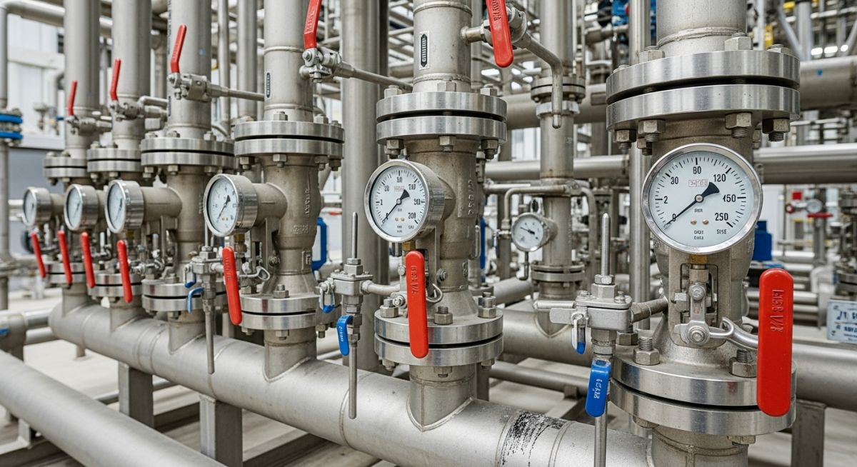
In my 20+ years of working in heavy industrial plants, I have seen how a single miscalculated pipe expansion loop can shut down an entire refinery. As a piping engineer, you are the architect of the plant’s circulatory system. You do not just connect point A to point B; you manage thermal expansion, high pressures, corrosive fluids, and structural integrity.
Whether you are designing a process piping system for a chemical plant or managing a pipeline network across a continent, this career demands a deep understanding of materials, stress analysis, and international codes. I wrote this guide to share the practical realities of this profession, the skills you need to master, and the career paths available to you.
Key Takeaways from a Senior Engineer
- Mastering stress analysis software like CAESAR II is a major career accelerator.
- A solid grasp of ASME B31.3 and ASME B31.1 is non-negotiable for safety and compliance.
- Field experience is just as valuable as 3D modeling skills; always verify your designs on-site.
Complete Course on
Piping Engineering
Check Now
Key Features
- 125+ Hours Content
- 500+ Recorded Lectures
- 20+ Years Exp.
- Lifetime Access
Coverage
- Codes & Standards
- Layouts & Design
- Material Eng.
- Stress Analysis
What Does a Piping Engineer Actually Do Daily?
My typical day as a piping engineer involves balancing safety, cost, and constructability. We translate Process Flow Diagrams (PFDs) and Piping and Instrumentation Diagrams (P&IDs) into physical 3D layouts. This requires calculating pipe wall thicknesses to withstand internal pressure, selecting the correct materials to prevent corrosion, and positioning supports to manage thermal expansion.
Let us look at the fundamental wall thickness calculation under ASME B31.3 Process Piping. The minimum required thickness, t, is calculated using the following formula:
Where:
- P = Internal design gauge pressure (psi or MPa)
- D = Outside diameter of the pipe (inches or mm)
- S = Allowable stress value for the material at design temperature (psi or MPa)
- E = Quality factor from ASME B31.3 tables
- W = Weld joint strength reduction factor
- Y = Coefficient from ASME B31.3 Table 304.1.1
Once the nominal thickness is selected, we must add corrosion and erosion allowances, plus a manufacturing tolerance (typically 12.5% for seamless pipes) to determine the final ordered schedule.
Thermal expansion is another major challenge. When a pipe heats up from ambient to operating temperature, it expands. The change in length is calculated as:
Where L is the initial length, alpha is the mean coefficient of thermal expansion, and dT is the temperature difference. If this expansion is restricted, it creates massive forces on equipment nozzles (like pumps and compressors), which can lead to catastrophic failures. We design expansion loops and offsets to absorb this movement safely.
Selecting the right material is critical for plant safety and longevity. Below is a reference table I use during the initial design phase to match process conditions with the correct material grades.
| Material Grade | Common Standard | Temperature Range | Typical Service Application |
|---|---|---|---|
| Carbon Steel | ASTM A106 Gr. B | -29°C to 427°C | Utility water, steam, non-corrosive hydrocarbons |
| Stainless Steel | ASTM A312 TP316 | -254°C to 815°C | Corrosive chemicals, high-purity systems, cryogenic fluids |
| Low Temp Carbon Steel | ASTM A333 Gr. 6 | -45°C to 343°C | Low-temperature process lines, cold climates |
| Alloy Steel | ASTM A335 Gr. P11/P22 | Up to 593°C | High-pressure, high-temperature superheated steam |
This matrix maps the core technical entities, acronyms, and physical parameters that every piping engineer must master to execute compliant designs.
| Entity / Acronym | Full Name / Parameter | Primary Code Reference | Engineering Significance |
|---|---|---|---|
| P&ID | Piping and Instrumentation Diagram | ISA 5.1 | The master schematic showing process flow, control loops, and safety boundaries. |
| NPS | Nominal Pipe Size | ASME B36.10M | Standard dimensionless designator for pipe diameter. |
| CAESAR II | Pipe Stress Analysis Software | ASME B31.3 / B31.1 | Industry-standard tool for calculating thermal, sustained, and occasional stresses. |
| MTO | Material Take-Off | Project Specific | Detailed list of piping components required for procurement and construction. |
How a Piping Engineer Verifies Site Layouts
Before any piping system is cleared for hydrotesting and commissioning, a field walkdown is mandatory. In my experience, what looks perfect in a 3D CAD model can have major interferences in the field due to structural tolerances or construction deviations. Use this checklist during your field walkdowns.
Field Walkdown & Verification Checklist
-
P&ID Compliance: Verify that all inline components, valves, instruments, and branch connections match the latest revision of the P&ID. -
Support Alignment: Ensure that pipe supports (guides, anchors, spring hangers) are installed exactly as specified in the stress isometric drawings. -
Valve Accessibility: Confirm that handwheels and chain operators are accessible for plant operators and do not block escape routes. -
Slope Verification: Check that lines requiring gravity flow (such as steam condensate or flare headers) have the correct slope specified in the drawings. -
Expansion Clearance: Verify that there is adequate physical clearance around expansion loops and elbows to allow for thermal movement without hitting structural steel.
Field Case Study: Real-World Application
The Problem: High-Pressure Steam Line Support Failure
During the commissioning of a co-generation plant, a 16-inch high-pressure steam line operating at 450°C experienced severe vibration and physical displacement. The line jumped off its primary sliding support, causing high bending moments on the steam turbine inlet nozzle. The turbine manufacturer threatened to void the warranty if the nozzle loads were not brought within API 611 / 612 limits immediately.
The Outcome: Redesign and Stress Mitigation
I led the engineering team to resolve this issue. We modeled the entire system in CAESAR II and discovered that the original designer had used rigid supports instead of variable spring hangers. This restricted the vertical thermal growth of the pipe, forcing it to lift off its horizontal guides. We replaced two rigid supports with variable spring hangers and added a directional guide. This reduced the turbine nozzle loads by 75%, bringing them well within safe limits and allowing the plant to start up safely.
Direct Recommendation: Always perform a comprehensive stress analysis on lines connected to sensitive rotating equipment. Never rely on standard support details for high-temperature or high-pressure systems.
Frequently Asked Engineering Questions
What is the difference between ASME B31.1 and ASME B31.3?
Why is pipe stress analysis necessary?
What software tools should a piping engineer learn?
What is the role of a piping engineer during construction?
How do you select the correct pipe schedule?
What is a piping isometric drawing?

📚 Recommended Resources: Piping Engineer
Read these Guides
🎓 Advanced Training


Related posts:
![A mechanical sucker rod pumpjack operating in an oil field at sunset]()
What is Sucker Rod Pump System in Oil Production?
![Piping material engineer reviewing technical specifications on a tablet in an industrial plant.]()
How a Piping Material Engineer Drives Industrial Project Success
![Industrial refinery plant showing various types of static equipment]()
What is Static Equipment? Types and List of Static Equipments
![Side-by-side comparison of industrial process piping and power plant steam piping systems.]()
Differences Between ASME B31.3 and B31.1: B31.3 vs B31.1
![Large industrial steel storage tank under construction with cranes and scaffolding]()
Storage Tank Construction Method Statement: Step-by-Step Engineering Guide
![Cutaway diagram of a globe control valve highlighting the internal valve trim components]()
What is a Valve Trim? Types, Components, and Selection


