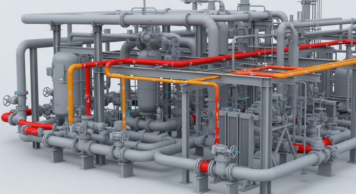
How to Develop a Piping Critical Line List for Stress Analysis
In my 20-plus years of piping engineering, I have seen projects succeed or fail based on how early and accurately the engineering team established their stress analysis boundaries. In the fast-paced environment of industrial plant design, there is a constant tug-of-war between piping designers who want to route lines quickly and stress engineers who need to ensure those lines do not tear themselves apart under thermal expansion. The peace treaty between these two factions is the piping critical line list.
Without a clearly defined, technically sound basis for selecting critical lines, you run two massive risks. Either you over-analyze your system—wasting hundreds of expensive engineering hours modeling low-risk utility lines in CAESAR II—or you under-analyze it, leaving high-risk process lines to fail during commissioning. I remember a project in a Middle Eastern refinery where a non-critical utility line was bypassed during formal review. During steam-out, that line expanded far beyond what the simple support scheme could handle, buckling a major structural beam. That is why getting this list right is not just a procedural step; it is a fundamental safety requirement.
Key Engineering Takeaways
- Understand the exact temperature, pressure, and diameter thresholds that trigger a formal stress analysis.
- Learn how to identify sensitive equipment connections that automatically classify a line as critical.
- Discover the mathematical basis behind flexibility checks using simplified code formulas.
- Establish a robust workflow for integrating the critical line list into your 3D modeling environment.
- Implement field-proven verification steps to prevent costly piping failures during plant commissioning.
What is a Piping Critical Line List?
Piping Critical Line List Definition: An essential design control ledger that segregates piping lines into critical and non-critical categories based on temperature, pressure, pipe diameter, and connected equipment sensitivity.
The primary purpose of this document is to define which lines must undergo formal computer-aided stress analysis (typically using software like CAESAR II or AutoPIPE) and which lines can be qualified using simplified methods or standard piping support guidelines. By establishing these boundaries early, the lead stress engineer can allocate resources efficiently, ensuring that high-risk systems receive the rigorous engineering scrutiny they require.
In my practice, we classify lines into three distinct analysis paths:
- Formal Analysis (Comprehensive): Computer-aided modeling to calculate forces, moments, stresses, and displacements at all nodes, ensuring compliance with ASME B31.3 limits.
- Simplified Analysis (Visual/Manual): Using simplified analytical methods, such as the Guided Cantilever Method, or standard span tables to verify flexibility without full computer modeling.
- Standard Support Rules: Applying standard project support details and spacing tables without performing individual stress calculations.
Never copy-paste a critical line list selection matrix from a previous project without verifying the design codes, site-specific seismic parameters, and equipment nozzle allowable limits. I have witnessed a project where a standard template was used for a plant in a high-seismic zone, resulting in the omission of several large-bore lines from formal analysis. The resulting field modifications cost the client over two hundred thousand dollars in structural reinforcements.
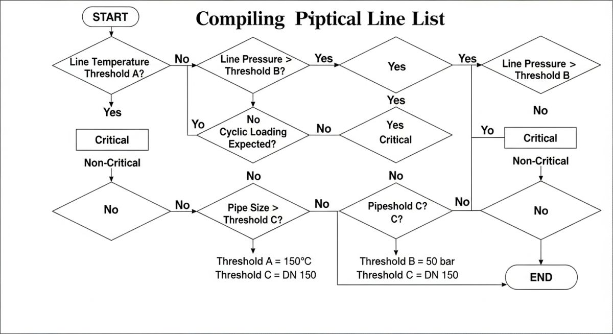
Engineering Basis for a Piping Critical Line List
Piping Critical Line List Basis: The technical framework derived from ASME B31.3 Paragraph 319 that establishes quantitative thresholds for temperature, pressure, and pipe diameter to mandate formal stress calculations.
The engineering basis for selecting critical lines is rooted in the physics of materials and the mechanical behavior of piping systems under load. When a pipe is subjected to temperature changes, it undergoes thermal expansion or contraction. If this movement is restricted by supports or connected equipment, high thermal stresses and nozzle loads are generated.
The fundamental equation governing thermal expansion is:
Where:
• dL = Change in pipe length (mm)
• L = Initial length of the pipe segment (m)
• alpha = Mean coefficient of thermal expansion of the material (mm/m/°C)
• dT = Difference between the design (or operating) temperature and the installation temperature (°C)
To determine if a piping system has adequate inherent flexibility to absorb this expansion without formal analysis, ASME B31.3 Paragraph 319.4.1 provides a simplified formula. A formal analysis is not required if the following criterion is met:
Where:
• D = Nominal pipe size (NPS) or outside diameter of the pipe (mm)
• y = Resultant of total displacement elements to be absorbed by the piping system (mm)
• L = Developed length of piping between anchors (m)
• U = Anchor distance (straight line between anchors) (m)
• K = A constant defined by the code, typically 208.3 for SI units (or 0.03 for US customary units)
If a piping system fails this simplified check, or if it exceeds the project-specific temperature and pressure thresholds, it must be added to the critical line list for formal computer-aided analysis.
The table below outlines the typical engineering thresholds used in major petrochemical and power generation projects to determine the level of stress analysis required. These values are based on standard carbon steel and low-alloy steel piping systems.
| Nominal Pipe Size (NPS) | Temperature Range (°C) | Pressure Limit (barg) | Required Stress Analysis Category |
|---|---|---|---|
| All Sizes | Below -29 or Above 400 | Any Pressure | Formal (Comprehensive Computer Model) |
| NPS 2 to NPS 6 | 150 to 300 | > 50 | Simplified / Formal if connected to Rotary Equipment |
| NPS 8 to NPS 12 | 100 to 250 | > 40 | Formal (Comprehensive Computer Model) |
| NPS 14 and Larger | Above 60 | Any Pressure | Formal (Comprehensive Computer Model) |
| Category M Fluids | Any Temperature | Any Pressure | Formal (Mandatory under ASME B31.3) |
This matrix maps the core technical entities, structural acronyms, and physical parameters that govern the development of a piping critical line list, along with their hyperlinked standard references.
| Entity / Acronym | Technical Definition | Physical Parameter / Limit | Reference Standard |
|---|---|---|---|
| CLL | Critical Line List | Project-specific master ledger | ASME B31.3 Appendix P |
| API 610 | Centrifugal Pumps for Petroleum, Petrochemical, and Natural Gas Industries | Nozzle load limits (Table 5) | API Standard 610 |
| API 617 | Axial and Centrifugal Compressors and Expander-compressors | Strict nozzle alignment and load limits | API Standard 617 |
| NEMA SM 23 | Steam Turbines for Mechanical Drive Service | Extremely low allowable nozzle forces and moments | NEMA SM 23 |
| EJMA | Expansion Joint Manufacturers Association | Bellows design and cycle life limits | EJMA Standards |
How Do We Classify Stress Critical Lines?
Stress Critical Line Classification: The systematic categorization of piping systems into distinct stress analysis categories based on their potential to cause catastrophic structural or equipment nozzle failures.
Before releasing a piping design for construction, the lead stress engineer must verify that every line on the critical line list has been modeled, analyzed, and approved. This checklist serves as the final quality gate to ensure that no critical line is missed during the design phase.
Piping Critical Line List Verification Checklist
-
Verify Equipment Connections: Ensure all lines connected to rotating equipment (pumps, compressors, turbines) are flagged as critical, regardless of operating temperature or pressure.
-
Check Relief Valve Discharge Lines: Confirm that all pressure relief valve (PRV) discharge lines, especially those venting to atmosphere, are included due to dynamic reaction forces.
-
Review Jacket Piping Systems: Verify that jacketed piping systems (e.g., sulfur lines) are classified as critical due to differential thermal expansion between the core and jacket.
-
Assess Seismic and Wind Loads: Ensure lines routed on high pipe racks in active seismic zones or high-wind areas are analyzed for environmental lateral loads.
-
Validate Expansion Joint Locations: Confirm that any line containing an expansion joint (bellows or slip joint) is on the critical list to verify guide spacing and anchor loads.
-
Cross-Reference with P&IDs: Perform a line-by-line audit matching the critical line list against the latest Piping and Instrumentation Diagrams (P&IDs) to catch any late-stage process changes.
Field Case Study: Real-World Application
During the commissioning of a 150 MW combined-cycle power plant, the field team noticed that the steam turbine casing was experiencing minor alignment shifts during warm-up. A quick investigation revealed that the 12-inch high-pressure steam inlet line was exerting forces on the turbine nozzle that exceeded the NEMA SM 23 allowable limits by over 300%.
Upon reviewing the project documentation, I discovered that this line had been omitted from the piping critical line list because a junior engineer had classified it as “standard utility piping” based solely on its operating pressure, ignoring the extreme operating temperature of 480°C and the highly sensitive nature of the turbine connection.
I immediately halted commissioning of that steam loop and pulled the line into CAESAR II for a rapid-response formal stress analysis. The original routing was a stiff, direct run with minimal flexibility. To resolve the issue without tearing out the entire pipe rack, we:
- Added a 3-dimensional expansion loop to absorb the thermal growth.
- Replaced two rigid guide supports with variable spring hangers to support the deadweight while allowing free thermal vertical movement.
- Installed a rigid anchor near the turbine nozzle to isolate the turbine from upstream pipe movements.
The redesigned system brought the nozzle loads down to 45% of the NEMA limit. The turbine was successfully aligned, commissioned, and has been operating trouble-free for over five years.
My direct recommendation from this experience is simple: Any line connected to rotating equipment with a design temperature above 65°C must be classified as critical. Do not let pressure-based classification rules blind you to the devastating effects of thermal expansion on sensitive machinery.
Frequently Asked Engineering Questions
What is the difference between a critical line and a non-critical line?
Does ASME B31.3 mandate a critical line list?
Why are lines connected to pumps and compressors always critical?
How does cyclic service affect critical line selection?
Can a small-bore line (under NPS 2) be on the critical line list?
Who is responsible for creating and approving the critical line list?
===FAQ_BLOCK===
Complete Course on
Piping Engineering
Check Now
Key Features
- 125+ Hours Content
- 500+ Recorded Lectures
- 20+ Years Exp.
- Lifetime Access
Coverage
- Codes & Standards
- Layouts & Design
- Material Eng.
- Stress Analysis