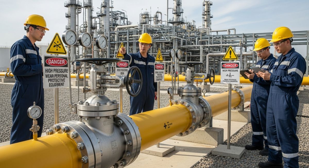
Pipeline Start-up and Commissioning: A Technical Engineering Guide
In my two decades of field experience, I have learned that the transition from construction to operation is the most volatile phase of any project. The start-up and commissioning of the pipeline is not merely a checklist exercise; it is a high-stakes engineering validation of every weld, gasket, and valve assembly under actual process conditions.
When we introduce process fluids into a system that has only seen air or nitrogen, we are testing the integrity of the entire design philosophy. My approach focuses on rigorous pre-commissioning, ensuring that mechanical completion is not just a signature on a document, but a verified state of readiness that minimizes risk to personnel and assets.
Key Takeaways for Commissioning Success:
- Strict adherence to ASME B31.3 pressure testing protocols.
- Validation of flow assurance models against real-time sensor data.
- Verification of safety instrumented systems (SIS) before fluid introduction.
- Systematic purging and inerting to prevent explosive atmospheres.
Technical Execution of Pipeline Start-up and Commissioning
Pipeline Start-up and Commissioning: The comprehensive engineering methodology used to transition a newly constructed pipeline from a static mechanical state to a dynamic, pressurized operational system while maintaining strict compliance with safety and environmental regulations.
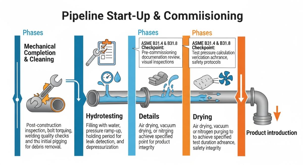
The technical foundation of commissioning relies on the transition from hydrostatic testing to operational readiness. Before any process fluid enters the line, we must perform a thorough mechanical integrity check. This involves verifying that all flange bolt torques meet the specifications defined in the piping class, and that all support systems are correctly adjusted to accommodate thermal expansion loads.
Pressure Testing and Integrity Verification
Hydrostatic testing is governed by ASME B31.4 or ASME B31.8 depending on the service. The test pressure is typically 1.25 to 1.5 times the design pressure. I always ensure that the test medium is compatible with the internal lining of the pipe to prevent corrosion initiation during the soak period.
Field Warning: Thermal Expansion Risks
During the initial fill, temperature differentials between the ambient pipe and the test fluid can induce significant thermal stress. Always monitor the pipe wall temperature and ensure the fluid temperature is within the range specified by the material toughness requirements to avoid brittle fracture, especially in low-temperature service lines.
Flow Assurance and System Purging
Once the integrity is confirmed, we move to dewatering and drying. For gas pipelines, the dew point must be strictly controlled to prevent hydrate formation. We utilize pigging trains with foam or mechanical pigs to displace water, followed by nitrogen purging to achieve an oxygen concentration below 1% by volume.
The calculation for nitrogen volume required for purging is: V_n = V_p * (1 + S), where V_p is the pipe volume and S is the safety factor (typically 1.5 to 2.0) to account for mixing at the interface. This ensures that the system is fully inerted before the introduction of hydrocarbons or reactive process chemicals.
Commissioning Strategy Evaluation: A balanced assessment of the technical benefits and operational risks associated with formal pipeline start-up procedures.
Advantages
- Early detection of construction defects before high-pressure operation.
- Verification of control loop response times under actual load.
- Validation of flow assurance models against real-world friction losses.
- Establishment of a baseline for future integrity management programs.
- Reduction of long-term maintenance costs through proactive leak detection.
Disadvantages
- High initial cost for specialized testing equipment and nitrogen.
- Extended project timelines due to rigorous safety hold points.
- Risk of equipment damage if commissioning procedures are bypassed.
- Complexity in managing hazardous waste from hydrotest water disposal.
- Potential for fatigue-related failures if pressure cycling is excessive.
Industrial Commissioning Scenarios: Critical applications where systematic start-up protocols are required to ensure safety and operational efficiency across diverse energy sectors.
High-Pressure Natural Gas Transmission
In gas transmission, commissioning involves complex pigging sequences to remove debris and moisture. We must ensure the pipeline is dried to a specific water vapor content to prevent hydrate formation, which could otherwise block the line during the first winter season of operation.
Refinery Feedstock Interconnects
Commissioning refinery piping requires strict adherence to chemical cleaning and passivation protocols. This ensures that the internal surfaces are free of mill scale and contaminants that could poison expensive catalysts in downstream processing units during the initial start-up phase.
Subsea Flowline Integration
Subsea commissioning is uniquely challenging due to the hydrostatic head and the need for remote intervention. We utilize specialized subsea test trees and ROV-operated valves to verify the integrity of the flowline-to-manifold connection before the production well is opened to the system.
Hydrogen Blending Infrastructure
As we transition to hydrogen-ready pipelines, commissioning must account for the high permeability and embrittlement risks of hydrogen. This requires specialized leak testing with helium tracers and rigorous monitoring of weld integrity to ensure the material can withstand the unique molecular behavior of hydrogen gas.
During the commissioning phase, establishing precise pressure and fluid parameters is non-negotiable for system integrity. Engineers must reference ASME B31.3 for process piping or ASME B31.4 for liquid transportation systems to ensure that test pressures do not exceed the yield strength of the pipe material. These parameters are calculated based on the maximum allowable operating pressure (MAOP) and the specific gravity of the commissioning medium, whether it be water, nitrogen, or the actual process fluid.
The following table outlines the critical thresholds for various pipeline diameters and service types. It is essential to note that these values assume a standard carbon steel material grade (e.g., API 5L X52). Any deviation in wall thickness or material yield strength requires a recalculation of the hoop stress using the Barlow formula to maintain safety margins during the initial pressurization sequence.
| Pipe Size (NPS) | Test Medium | Target Pressure (Bar) | Hold Time (Hours) |
|---|---|---|---|
| 6 – 12 | Water (Hydrotest) | 1.5 x Design | 4.0 |
| 14 – 24 | Nitrogen (Pneumatic) | 1.1 x Design | 8.0 |
| 24+ | Water (Hydrotest) | 1.25 x Design | 24.0 |
Effective pipeline commissioning requires a structured approach to managing technical entities and their associated regulatory standards. By mapping these components, we ensure that every valve, flange, and instrumentation loop is verified against its design specification before the introduction of hazardous hydrocarbons. This matrix serves as a high-level reference for project managers and field engineers to track compliance across diverse system components.
The matrix below categorizes critical assets by their function, the relevant engineering standard, and the primary physical parameter monitored during the start-up sequence. Maintaining this level of documentation is vital for the final handover to the operations team, as it provides a clear audit trail of the system’s performance during the initial commissioning phase.
| Entity | Standard | Parameter |
|---|---|---|
| Isolation Valves | API 6D | Leakage Rate |
| Pressure Relief | API 526 | Set Pressure |
| Flange Joints | ASME B16.5 | Torque Value |
Before initiating the flow of process fluids, a rigorous site verification process must be completed. This checklist ensures that all mechanical, electrical, and instrumentation systems are aligned with the design intent and safety requirements. Failure to verify these items can lead to catastrophic equipment failure or environmental incidents during the start-up phase.
-
Mechanical Completion: Confirm all piping supports are installed per ASME B31.3 and that all temporary blinds used for hydrotesting have been removed. -
Instrumentation Calibration: Verify that all pressure transmitters and flow meters are calibrated and loop-checked to the control room (DCS/SCADA). -
Safety Systems: Ensure Emergency Shutdown (ESD) valves are functional and that the logic sequence matches the Cause and Effect matrix. -
Cleaning and Purging: Confirm the pipeline has been pigged and purged with nitrogen to achieve the required dew point and oxygen concentration levels. -
Documentation Audit: Ensure all NDT reports, weld logs, and pressure test certificates are signed off by the authorized inspector.
Each item on this list must be signed off by the lead commissioning engineer. If any item fails verification, the start-up sequence must be halted immediately until corrective actions are implemented and re-verified. This process is the final line of defense in maintaining the integrity of the pipeline infrastructure.
Problem: Unexpected Pressure Drop During Nitrogen Purging
- Failure to identify a partially closed manual isolation valve in a bypass line.
- Inadequate monitoring of the nitrogen supply pressure at the injection point.
- Incorrect calculation of the purge volume leading to premature termination of the cycle.
- Lack of real-time pressure differential monitoring across the pipeline segment.
Outcome: Successful System Stabilization and Handover
- Implemented a secondary pressure monitoring station at the mid-point of the pipeline.
- Revised the purge procedure to include a mandatory valve position verification step.
- Achieved the target oxygen concentration of less than 0.5 percent within 48 hours.
- Successfully transitioned the pipeline to the operational phase without further pressure anomalies.
My recommendation for similar projects is to always utilize redundant pressure sensors during the purging phase. Relying on a single point of measurement often masks localized flow restrictions that can lead to significant delays in the commissioning schedule.
What is the primary purpose of a hydrotest?
- Defects in weld joints or base material that were not detected during non-destructive testing.
- Mechanical failures in flange gaskets or valve seals.
- Structural weaknesses in the piping supports or anchor points.
This procedure is mandated by ASME B31.3 to ensure the safety of personnel and the environment during the life of the asset.
How do you manage flow assurance during start-up?
- Pre-heating the pipeline segment if the ambient temperature is below the pour point of the fluid.
- Injecting chemical inhibitors such as methanol or glycol to lower the hydrate formation temperature.
- Maintaining a steady flow velocity to prevent the settling of solids or water accumulation in low-lying sections.
These measures are critical for avoiding costly blockages that often require mechanical intervention or chemical remediation.
What are the risks of pneumatic testing?
- High-velocity shrapnel that can cause severe injury or death to personnel in the vicinity.
- Extensive damage to surrounding infrastructure and equipment.
- Uncontrolled release of the test medium, which may be hazardous if it is not inert.
Because of these risks, ASME B31.3 requires strict safety protocols, including a minimum clearance distance and the use of remote monitoring equipment during the test.
Why is nitrogen purging necessary?
- It prevents internal corrosion by removing water vapor that could react with the steel.
- It ensures that the process fluid is not contaminated by air, which could affect product quality.
- It provides a stable, inert environment for the initial start-up sequence.
The process is continued until the oxygen concentration is reduced to a safe level, typically below 0.5 percent by volume.
How do you verify valve integrity?
- Bubble-tight leakage tests to ensure the valve can isolate sections of the pipeline effectively.
- Full-stroke operation tests to verify that the actuator and control system are correctly configured.
- Torque verification to ensure that the valve can be operated under the design pressure conditions.
These tests are performed in accordance with API 6D standards to guarantee that the valves will perform as expected during emergency shutdown scenarios.
What is the role of the pigging process?
- Improved flow efficiency by removing internal obstructions.
- Verification of the pipeline geometry to ensure there are no dents or buckles.
- Removal of standing water that could cause corrosion or hydrate formation.
This process is a fundamental step in the commissioning sequence, ensuring that the pipeline is ready for long-term, reliable operation.
📚 Recommended Resources: Pipeline Start-up and Commissioning
Complete Course on
Piping Engineering
Check Now
Key Features
- 125+ Hours Content
- 500+ Recorded Lectures
- 20+ Years Exp.
- Lifetime Access
Coverage
- Codes & Standards
- Layouts & Design
- Material Eng.
- Stress Analysis
