Table of Contents

How Do Pipe Ferrules Ensure Leak-Free Industrial Piping Systems?
In my 20 years of managing high-pressure piping installations, I have seen minor components cause major catastrophes. I remember a cold morning at a hydrogen generation plant where a single mismatched compression fitting shut down an entire process train. The culprit was not a ruptured pipe or a blown valve body; it was a tiny, improperly swaged ferrule.
These small, conical rings are the unsung heroes of instrumentation and process piping. When you tighten a compression nut, you are initiating a highly engineered mechanical deformation process. The ferrule bites into the tubing wall, creating a metal-to-metal seal that can withstand extreme pressures, thermal cycling, and intense vibration. Understanding how to select, install, and inspect these components is what separates a reliable facility from a maintenance nightmare.
- Double-ferrule designs separate the sealing function from the mechanical gripping action, providing superior vibration resistance.
- Interchanging ferrules from different manufacturers alters the swaging geometry and leads to premature joint failure.
- Proper material selection requires the ferrule to be softer than the tubing to achieve a gas-tight mechanical bite.
Complete Course on
Piping Engineering
Check Now
Key Features
- 125+ Hours Content
- 500+ Recorded Lectures
- 20+ Years Exp.
- Lifetime Access
Coverage
- Codes & Standards
- Layouts & Design
- Material Eng.
- Stress Analysis
Why Are Pipe Ferrules Used in Piping?
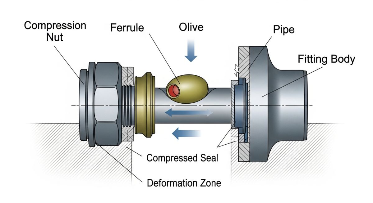
To appreciate the engineering behind ASME B31.3 Process Piping systems, we must look at the mechanics of the swaging process. When torque is applied to the fitting nut, it drives the ferrule axially into the fitting body’s angled cam. This forces the leading edge of the ferrule radially inward, biting into the outer diameter of the tube.
Single Ferrule vs. Double Ferrule Mechanics
Single-ferrule systems use one component to handle both the sealing and the gripping. While cost-effective for low-pressure utility lines, they are susceptible to vibration fatigue. The rear edge of a single ferrule can act as a stress riser, concentrating bending stresses directly at the bite point.
Double-ferrule systems split these duties. The front ferrule creates the primary seal against the fitting body and the tube outer diameter. The rear ferrule performs the mechanical grip, hinging inward to clamp the tube securely without transferring torque or stress to the sealing interface. This dual-action mechanism isolates the seal from system vibrations and thermal expansion.
Engineering Calculations: Swaging Force and Torque
The axial force (F_a) required to swage a ferrule onto a tube is a function of the applied torque (T), the nominal thread diameter (d), and the torque coefficient (K):
Once the axial force is established, the contact pressure (P_c) at the ferrule-to-tube interface must exceed the yield strength (sigma_y) of the tubing material to achieve plastic deformation:
Where dm is the mean diameter of the contact zone and w is the contact width. If the tubing material is harder than the ferrule, the ferrule will deform outward instead of biting inward, resulting in a joint that will blow out under pressure.
Never mix components from different manufacturers. A Swagelok front ferrule paired with a Parker rear ferrule or fitting body alters the swaging geometry. This mismatch prevents the correct hinge-and-collet action, leading to catastrophic bypass leaks under high pressure.
What Materials Make Pipe Ferrules Reliable?
Selecting the correct material is a balancing act between corrosion resistance, mechanical strength, and hardness. The table below outlines the standard materials used in industrial process lines.
| Ferrule Material | Max Hardness (HRB) | Temp Range (°F) | Compatible Tubing | Standard Specification |
|---|---|---|---|---|
| 316 Stainless Steel | 80 HRB | -325 to 1000 | Fully Annealed 316SS | ASTM A269 |
| Brass (Alloy 360) | 60 HRB | -40 to 400 | Copper / Soft Brass | ASTM B16 |
| Monel 400 | 75 HRB | -325 to 800 | Monel Alloy 400 Tubing | ASTM B164 |
| PTFE (Teflon) | N/A (Soft) | -100 to 150 | PFA / FEP / PTFE | ASTM D1710 |
This matrix maps the relationship between system parameters, design codes, and the physical characteristics of the ferrule assembly.
| System Parameter | Acronym | Physical Metric | Applicable Standard |
|---|---|---|---|
| Maximum Allowable Working Pressure | MAWP | PSI / Bar | ASME B31.3 Chapter IX |
| Outer Diameter of Tubing | OD | Inches / Millimeters | ASME B36.10M |
| Vibration Fatigue Limit | VFL | Hertz / Cycles | ASTM F1387 |
How to Install Pipe Ferrules Correctly?
A perfect installation relies on precision. Skipping a single step in the preparation phase can lead to a micro-leak path that is difficult to detect until the system is fully pressurized.
-
Tube Cut Squareness: Ensure the tube is cut within +/- 1 degree of square using a dedicated tube cutter. Do not use a hacksaw.
-
Deburring (Internal & External): Remove all burrs from both the inside and outside of the tube end. Leftover metal shavings will damage the ferrule seating surface.
-
Bottoming Out: Insert the tube fully into the fitting body until it bottoms out against the internal shoulder. Mark the tube at the back of the nut to verify it does not slip during tightening.
-
Nut Tightening (The 1-1/4 Turn Rule): For sizes 1/4 inch to 1 inch, tighten the nut finger-tight, then rotate it exactly 1-1/4 turns with a wrench while holding the fitting body stationary.
-
Gap Gauge Verification: Use a manufacturer-approved gap inspection gauge to verify that the space between the nut and the fitting body is within tolerance.
Field Case Study: Real-World Application
During the commissioning of a high-pressure hydrogen manifold operating at 6,500 PSI, the inspection team detected a persistent gas leak. The system used 1/2-inch 316 Stainless Steel tubing. Upon disassembly, I discovered that the field technicians had mixed Swagelok fitting bodies with generic import ferrules. The import ferrules had a slightly different taper angle, which prevented the rear ferrule from swaging correctly. This created a micro-gap along the tube surface, allowing hydrogen gas to bypass the seal.
We immediately halted commissioning and replaced the compromised joints with single-source, certified 316 Stainless Steel double-ferrule assemblies. We implemented a strict site rule: all compression fittings must be verified using a gap inspection gauge before pressurization. The manifold was re-tested at 1.5 times the design pressure (9,750 PSI) and achieved a 100% leak-tight seal, saving the project from costly operational delays.
My recommendation for any high-pressure or hazardous gas service is to establish a strict material control program. Store fittings and ferrules in their original, labeled packaging, and train your craft personnel on the mechanical differences between single and double ferrule designs.
Frequently Asked Engineering Questions
Can you reuse a pipe ferrule once it has been swaged?
Why must the ferrule material be softer than the tubing?
What is the difference between a single and a double ferrule?
How do you identify an over-tightened ferrule joint?
Are plastic ferrules suitable for industrial chemical lines?
What standards govern the testing of compression ferrules?

📚 Recommended Resources: pipe ferrules
Read these Guides
Related posts:
![Industrial metallic piping network with stainless steel pipes and valves in a processing plant.]()
What is Metallic Piping: Types, Advantages, Applications, and ASTM Standards
![Industrial gas processing facility comparing cryogenic LNG storage tanks and pressurized LPG bullet tanks.]()
What are the Differences Between LNG and LPG?
![Split-screen comparison of liquid oil failing under extreme heat versus dry graphite lubricating a mechanical bearing smoothly.]()
Why Is Graphite a Better Lubricant Than Oil in Industrial Piping?
![Tall industrial distillation column tower at a chemical processing plant]()
What is a Distillation Column? Working Principles and Types
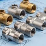
![Close-up of various metal pipe fittings with different thread types on an engineering blueprint.]()
Understanding the Different Types of Pipe Threads in Piping Systems
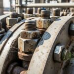
![Close-up of heavy-duty industrial piping fasteners securing a steel flange joint.]()
Piping Fasteners: Engineering Selection, Torque Calculations, and Installation Standards