What is a Compression Fitting and How Does It Work?
In my 20 years of managing piping installations across petrochemical plants and offshore rigs, I have seen many mechanical joints fail due to poor selection or incorrect installation. The compression fitting is one of the most versatile, reliable, and flame-free joint designs available to modern piping engineers. Unlike threaded or welded connections, these fittings allow for rapid assembly and disassembly while maintaining an exceptional seal under high-pressure and high-vibration conditions.
Understanding the mechanics of how these components interact is the difference between a system that runs flawlessly for decades and one that suffers catastrophic blowouts. In this guide, I will share my field experience regarding the design, selection, and installation of these critical components.
Key Engineering Takeaways
- Learn the mechanical principles governing single and double-ferrule designs.
- Understand torque-to-tension conversion and contact pressure calculations.
- Identify the correct material combinations to prevent galvanic corrosion and galling.
- Master the step-by-step installation procedure to eliminate field failures.
Complete Course on
Piping Engineering
Check Now
Key Features
- 125+ Hours Content
- 500+ Recorded Lectures
- 20+ Years Exp.
- Lifetime Access
Coverage
- Codes & Standards
- Layouts & Design
- Material Eng.
- Stress Analysis
How Does a Compression Fitting Work Safely?
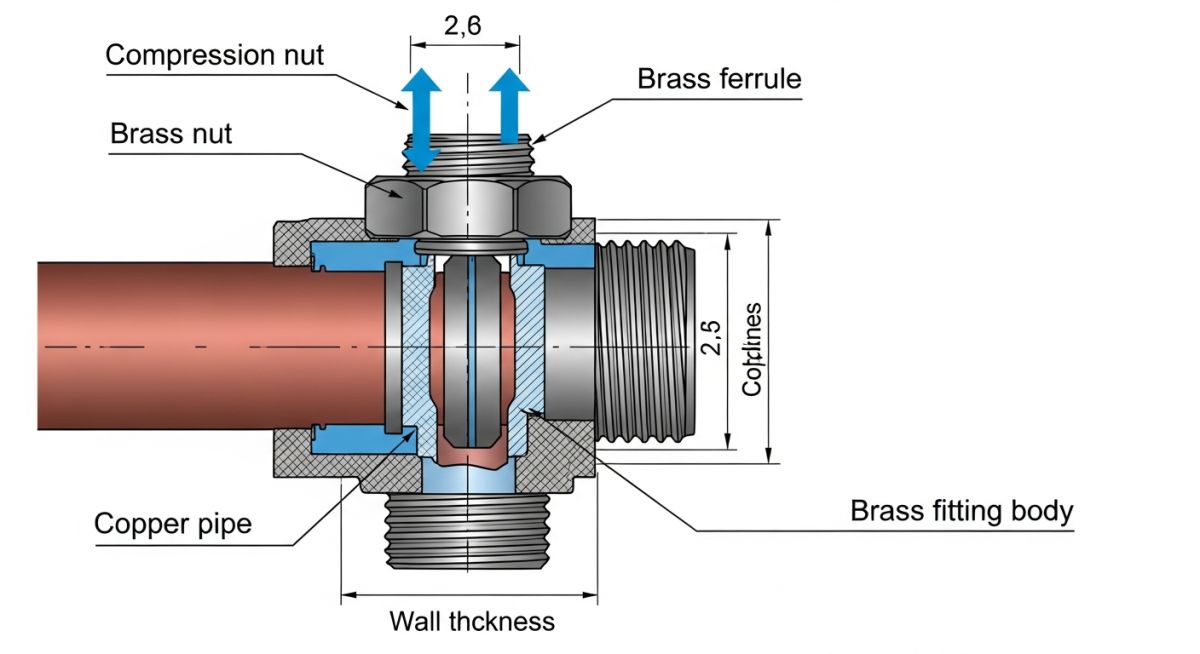
Mechanical Joint Sealing: The process of creating a pressure-retaining barrier by tightening a nut to drive a ferrule into a tapered body. This action deforms the ferrule radially to grip and seal the tube surface under ASME B31.1 guidelines.
To appreciate the reliability of a compression fitting, we must look at the physics of the joint. When you tighten the compression nut onto the fitting body, you convert rotational torque into axial force. This axial force drives the ferrule forward into the angled camming mouth of the fitting body.
As the ferrule moves along this taper, it is compressed radially inward. This radial compression causes the leading edge of the ferrule to bite into the outer diameter of the tubing. This bite creates a mechanical shoulder that prevents the tube from blowing out under pressure, while simultaneously forming a highly concentrated metal-to-metal seal.
Never mix nuts, ferrules, or bodies from different manufacturers. Even though a Swagelok nut might thread onto a Parker or Gyrolok body, the internal angles, tolerances, and material hardness profiles differ. Intermixing components compromises the mechanical grip, leading to sudden, catastrophic blowouts under pressure. Always source complete assemblies from a single manufacturer.
The Engineering Mathematics of the Joint
The torque applied to the nut must overcome thread friction and the resistance of the ferrule deformation. The relationship between applied torque (T) and the resulting axial force (Fa) is expressed by the standard torque equation:
Where:
• T = Applied torque (N-m or lb-in)
• k = Torque coefficient (typically 0.15 to 0.20 for dry threads, and lower for lubricated threads)
• d = Nominal thread diameter (m or in)
• Fa = Axial force (N or lbs)
The contact pressure (Pc) generated at the ferrule-to-tube interface must exceed the internal fluid pressure (Pi) by a factor of at least 1.5 to ensure a gas-tight seal. The hoop stress (Sh) induced in the tubing during this process must not exceed the yield strength of the tube material to prevent localized collapse:
Where Do is the outer diameter of the tube and t is the wall thickness. If the tube wall is too thin, the ferrule will crush the tube rather than biting into it. If the tube wall is too thick or the material is too hard, the ferrule cannot achieve the depth of bite required for a secure mechanical grip.
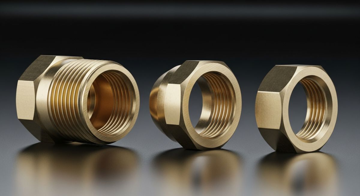
What Are the Main Compression Fitting Types?
Compression Fitting Classifications: The categorization of mechanical joints based on ferrule configuration, material composition, and pressure rating. These variations accommodate diverse industrial applications from low-pressure instrumentation to high-pressure hydraulic systems.
In my practice, I classify these fittings into two primary mechanical designs: single-ferrule and double-ferrule systems. Selecting the correct design depends entirely on your system’s pressure, temperature, and vibration profile.
1. Single-Ferrule Fittings
Often referred to as compression joints in domestic plumbing, the single-ferrule design uses a single, symmetrical ring. As the nut is tightened, the ferrule compresses at both ends, sealing against the fitting body and gripping the tube simultaneously. While highly cost-effective, they are susceptible to vibration-induced loosening and are generally limited to low-to-medium pressure applications (up to 2,000 PSI depending on size and material).
2. Double-Ferrule Fittings
This is the gold standard for industrial instrumentation and high-pressure process lines. The system splits the mechanical duties between two distinct components:
• The Front Ferrule: Designed to create the primary seal against the fitting body and the outer diameter of the tube.
• The Back Ferrule: Engineered to mechanically grip the tube, preventing axial movement and absorbing system vibration.
The double-ferrule design prevents torque transmission to the tubing during installation, ensuring that the tube does not twist or stress internal components. These fittings can safely handle pressures exceeding 10,000 PSI when paired with heavy-wall stainless steel tubing.
The following table outlines the maximum allowable working pressures and recommended installation torque values for 316 Stainless Steel double-ferrule fittings. These values are calculated in accordance with ASME B31.3 Process Piping guidelines, assuming fully annealed high-quality tubing.
| Tube OD (Inches) | Wall Thickness (Inches) | Max Working Pressure (PSI) | Recommended Installation Torque (N-m) | Turns from Finger-Tight |
|---|---|---|---|---|
| 1/4″ | 0.035″ | 5,100 | 15 – 18 | 1-1/4 Turns |
| 3/8″ | 0.049″ | 4,800 | 25 – 30 | 1-1/4 Turns |
| 1/2″ | 0.065″ | 4,700 | 45 – 50 | 1-1/4 Turns |
| 3/4″ | 0.095″ | 4,600 | 75 – 85 | 1-1/4 Turns |
| 1″ | 0.109″ | 4,000 | 110 – 130 | 1-1/2 Turns |
This matrix maps the core technical entities, structural acronyms, and physical parameters of compression fittings to their corresponding industry standards and design codes.
| Component / Parameter | Primary Material | Governing Standard | Key Design Function |
|---|---|---|---|
| Fitting Body | ASTM A182 (SS316) / ASTM B16 (Brass) | ASME B16.34 | Houses the internal seat and guides the ferrule assembly. |
| Front Ferrule | Fully Annealed SS316 / Brass | ASTM F1387 | Creates the primary fluid seal against the body and tube. |
| Back Ferrule | Case-Hardened SS316 | Manufacturer Proprietary | Grips the tube to prevent axial blowout under pressure. |
| Compression Nut | ASTM A276 (SS316) / Brass | ASME B1.1 (Threads) | Translates rotational torque into axial clamping force. |
How to Install a Compression Fitting Correctly?
Compression Joint Installation: The systematic procedure of cutting, deburring, inserting, and tightening a mechanical fitting to ensure a leak-free seal. Proper execution prevents tube blowout and galling under high-pressure operating conditions.
In my experience, over 90% of field leaks are caused by poor installation practices rather than component defects. Following a strict, standardized checklist is the only way to guarantee joint integrity across thousands of connections on a project site.
Field Quality Control Checklist
-
Tube Cut Squareness: Ensure the tubing is cut square within +/- 1 degree using a dedicated tube cutter. Do not use a hacksaw, as it creates excessive burrs and uneven ends.
-
Internal & External Deburring: Remove all burrs from both the inside and outside of the tube end. Leftover metal shavings can damage the ferrule or enter the process stream.
-
Bottoming Out: Insert the tube fully into the fitting body until it bottoms out firmly against the internal shoulder. If not fully bottomed, the ferrule will deform without gripping the tube correctly.
-
Marking & Tightening: Scribe a line on the nut and body at the finger-tight position. Tighten the nut exactly 1-1/4 turns (or 3/4 turn for sizes under 1/4″) using a backup wrench to prevent the body from rotating.
-
Gap Inspection Gauge: Use a manufacturer-approved gap inspection gauge to verify that the nut has been sufficiently tightened. If the gauge fits in the gap, the fitting is under-tightened.
Field Case Study: Real-World Application
During the commissioning of a refinery hydrotreater unit, the field team reported persistent micro-leaks on the 3/8″ stainless steel hydrogen gas instrumentation lines. The system operated at 3,200 PSI. Initial inspection revealed that the contractors had used a mix of single-ferrule brass fittings and double-ferrule stainless steel fittings from two different manufacturers. Furthermore, several joints were under-tightened because the technicians feared crushing the thin-walled tubing.
I ordered an immediate halt to the installation and implemented a complete system audit. We replaced all mixed-manufacturer fittings with single-source, double-ferrule 316 Stainless Steel fittings. We trained the technicians on the “turns-from-finger-tight” method and mandated the use of gap inspection gauges. After re-assembling the lines and performing a helium leak test, the system achieved 100% leak-tight integrity, saving the project from costly startup delays.
My direct recommendation for any high-pressure gas application is to always specify double-ferrule stainless steel fittings, enforce strict material compatibility rules, and never rely on technician guesswork for torque values.
Frequently Asked Engineering Questions
Can compression fittings be reused after disassembly?
What is the maximum pressure a compression fitting can handle?
Why do compression fittings leak on copper pipes?
Do I need to use Teflon tape on compression threads?
How do I prevent galling on stainless steel fittings?
What is the difference between NPT and compression fittings?

📚 Recommended Resources: compression fitting
Read these Guides


Related posts:
![Professional surveyor conducting Topographical Surveys for Solar Projects on a large-scale utility site with complex terrain.]()
Topographical Surveys for Solar Projects: A Technical Engineering Guide
![A geotechnical drill rig performing soil sampling on a large, open field intended for a utility-scale solar farm project.]()
Geotechnical Investigation for Solar Farms: Essential Site Design Guide
![Isometric site plan showing Utility Corridor Planning for Data Centres with color-coded power, water, and telecom infrastructure paths.]()
Utility Corridor Planning for Data Centres: A Strategic Engineering Guide
![Aerial view of a data centre site showcasing perimeter drainage systems, detention basins, and site grading for flood prevention.]()
Drainage Design Considerations for Data Centres: A Technical Guide
![Professional surveyor using a Total Station on a large data centre construction site for topographical mapping.]()
Topographical Surveys for Data Centre Projects: A Technical Guide
![Cross-section diagram showing Ground Improvement for Data Centres using stone columns and deep soil mixing beneath a concrete foundation slab.]()
Ground Improvement for Data Centres: Engineering Stability and Settlement Control