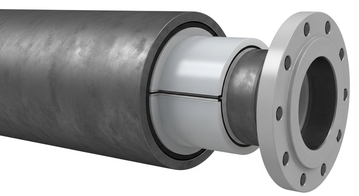
Design Guidelines for PE & ROTO Lined Carbon Steel Piping
In my two decades of managing aggressive chemical process units, I have found that selecting the right lining technology is the difference between a ten-year service life and a catastrophic failure. PE and ROTO lined carbon steel piping systems represent the industry standard for handling highly corrosive media, yet they are frequently misunderstood during the design phase.
Designers often overlook the critical interaction between the thermal expansion coefficients of the steel carrier and the thermoplastic liner. If you do not account for the differential movement, you risk liner collapse or buckling during thermal cycling. This guide provides the technical framework to ensure your piping specifications align with current industry best practices for longevity and safety.
Key Takeaways for Engineers:
- Understand the vacuum rating limitations inherent to loose-lined PE systems.
- Master the flange sealing requirements to prevent liner creep at connection points.
- Apply correct thermal expansion compensation to avoid liner buckling.
- Ensure carbon steel carrier pipe wall thickness meets structural requirements independent of the liner.
Technical Design Guidelines for PE & ROTO Lined Carbon Steel Piping
Lined Piping Design: The systematic integration of thermoplastic liners within carbon steel pressure boundaries, requiring rigorous adherence to ASTM F1545 standards for performance and safety.
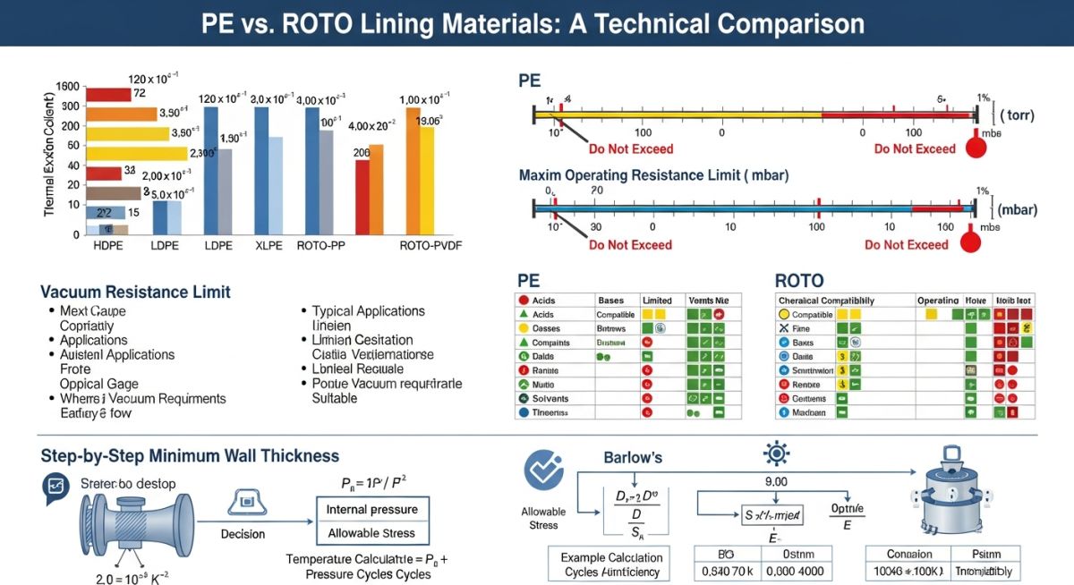
When designing for PE and ROTO lined carbon steel piping, the first priority is the structural integrity of the steel carrier. Per ASME B31.3, the steel pipe must be designed to withstand the full internal pressure of the process fluid. The liner is considered a non-pressure-retaining component. You must specify the steel wall thickness based on the design pressure and temperature, ignoring any structural contribution from the liner.
Vacuum rating is the most common failure point in PE-lined systems. Because PE is a loose liner, it is susceptible to collapse under vacuum conditions. You must calculate the collapse pressure using the modulus of elasticity of the liner material at the maximum operating temperature. If the system experiences vacuum, you must specify a bonded ROTO lining or incorporate vacuum-rated reinforcement, such as a perforated liner or a vacuum-rated mesh.
Field Warning: Thermal Cycling Risks
Thermoplastic liners have a coefficient of thermal expansion significantly higher than carbon steel. During cooling cycles, the liner contracts faster than the steel, which can lead to “liner pull-back” at the flange faces. Always specify flared liner ends that extend over the flange face to create a self-gasketing seal, ensuring the liner is captured between the mating flanges.
For ROTO lining, the process involves rotating the steel pipe while heating it, then introducing the thermoplastic powder. This creates a seamless, uniform coating that is mechanically locked to the steel surface. This method is superior for complex geometries like tees and elbows where PE extrusion might result in thinning at the outer radius. Ensure your specification requires a spark test (holiday detection) at 15kV to verify the integrity of the ROTO lining before installation.
Flange sealing is critical. Because the liner acts as the gasket, you must ensure the flange faces are smooth and free of burrs. Over-torquing the bolts can crush the liner, while under-torquing leads to leakage. Always follow the manufacturer’s torque sequence and values, which are typically lower than those for standard metallic gaskets to prevent cold flow of the thermoplastic material.
Lined Piping Performance: A critical evaluation of operational benefits versus mechanical limitations in corrosive service environments.
Advantages
- Exceptional chemical resistance against acids, bases, and solvents.
- Lower total cost of ownership compared to exotic alloys like Hastelloy or Titanium.
- Smooth internal surface reduces pressure drop and prevents scaling/fouling.
- ROTO lining provides seamless protection for complex fittings and geometries.
- Excellent electrical insulation properties for preventing galvanic corrosion.
Disadvantages
- Strict temperature limitations based on the specific thermoplastic material.
- Susceptibility to vacuum collapse in loose-lined PE configurations.
- Liner damage during field cutting or welding of the steel carrier.
- Thermal expansion mismatch requires careful stress analysis and support design.
- Limited repairability; damaged liners often require full spool replacement.
Lined Piping Deployment: Strategic implementation of corrosion-resistant piping in high-demand industrial sectors requiring long-term material stability.
Chemical Processing Plants
Used extensively for transporting concentrated hydrochloric and sulfuric acids where metallic piping would corrode within months. The inert nature of the PE/ROTO liner ensures product purity and prevents metallic contamination of the process stream.
Water Treatment Facilities
Employed for handling aggressive chemical dosing lines, including sodium hypochlorite and ferric chloride. The smooth bore of the lined pipe prevents the buildup of mineral deposits, maintaining consistent flow rates over extended operational cycles.
Pharmaceutical Manufacturing
Utilized in high-purity fluid transfer systems where non-leaching characteristics are mandatory. The seamless ROTO lining prevents stagnant zones where bacteria could proliferate, meeting stringent sanitary design requirements for clean-in-place systems.
When selecting lining materials for carbon steel piping, engineers must reconcile the mechanical strength of the steel carrier pipe with the chemical resistance of the polymer liner. The following table outlines the standard pressure-temperature ratings for common lining materials, assuming adherence to ASME B31.3 guidelines for metallic components. Note that the effective pressure rating of the assembly is limited by the lower of the two components: the steel flange rating or the liner’s thermal deformation limit.
Designers should prioritize these values when specifying systems for corrosive chemical transport. Always verify that the vacuum rating of the liner is sufficient for the specific process conditions, as ROTO-lined systems often exhibit different collapse resistance compared to loose-lined PE systems. The data below assumes standard schedule 40 carbon steel backing.
| Lining Material | Max Temp (C) | Vacuum Rating (Bar) | Chemical Resistance |
|---|---|---|---|
| HDPE (PE) | 80 | 0.5 | Excellent (Acids/Bases) |
| PTFE (ROTO) | 200 | 0.1 | Universal (Solvents/Strong Oxidizers) |
| PFA (ROTO) | 230 | 0.1 | High Purity/High Temp |
The following matrix maps the critical engineering entities involved in the specification of lined piping systems. By aligning these parameters with international standards, we ensure that the structural integrity of the carbon steel carrier pipe is never compromised by the thermal expansion or chemical permeation characteristics of the internal liner.
This mapping is essential for procurement and quality assurance teams to verify that the selected materials meet the project’s specific corrosion allowance and pressure containment requirements. Refer to ASTM standards for material testing protocols associated with these entities.
| Entity | Standard | Primary Function |
|---|---|---|
| Carrier Pipe | ASTM A106 | Pressure containment and structural support |
| Liner Material | ASTM F1545 | Corrosion barrier and chemical inertness |
| Flange Sealing | ASME B16.5 | Leak prevention at joints |
Verification of lined piping systems requires a rigorous approach to ensure that the liner has not been damaged during transport or installation. In my experience, the most common failures occur at the flange faces where the liner must be flared or sealed to prevent media contact with the steel backing. This checklist serves as a mandatory guide for site engineers to validate the integrity of the installation before commissioning.
- 1. Visual Inspection: Check for any visible cuts, gouges, or surface irregularities in the liner bore.
- 2. Flange Face Integrity: Ensure the liner flare is smooth, free of cracks, and covers the entire gasket seating area.
- 3. Vacuum Rating Check: Confirm that the system design accounts for potential vacuum conditions to prevent liner collapse.
- 4. Bolt Torque Verification: Use calibrated torque wrenches to meet the manufacturer’s specific requirements for lined flange joints.
- 5. Grounding Continuity: Verify that the conductive lining (if specified) is properly grounded to prevent static discharge.
Always document the torque values for every flange connection. If a liner shows signs of deformation or “cold flow” at the flange face, it must be replaced immediately. Never attempt to repair a damaged liner with field-applied coatings, as these will not provide the required chemical resistance or structural bond to the carbon steel carrier.
Problem: Premature Liner Failure in Acid Service
- Rapid degradation of the liner at the flange interface.
- Inconsistent bolt torque leading to uneven compression of the liner flare.
- Thermal cycling causing the liner to pull back from the flange face.
- Lack of proper support for the heavy-duty lined piping sections.
Outcome: Successful Remediation and System Longevity
- Implemented a strict torque-sequence protocol for all flange connections.
- Installed thermal expansion loops to mitigate stress on the liner.
- Switched to a higher-grade PFA liner for improved thermal stability.
- Achieved a 40% increase in service life compared to the previous installation.
My recommendation for similar projects is to prioritize the selection of the liner material based on the maximum process temperature, not the average operating temperature. Thermal expansion is the primary enemy of lined piping; if the steel and the liner expand at different rates, the liner will eventually fail at the weakest point, which is almost always the flange connection.
What is the primary difference between PE and ROTO lining?
- PE is cost-effective for water and mild chemical transport.
- ROTO lining provides superior chemical resistance for aggressive acids.
- ROTO processes allow for complex geometries that are difficult to line with standard PE sleeves.
How does vacuum affect lined piping design?
- Always specify vacuum-rated liners for processes involving suction pumps.
- Use perforated liners or vacuum-resistant bonding agents where necessary.
- Consult ASTM F1545 for specific vacuum testing requirements for lined components.
Can I weld on a lined pipe?
- The heat from welding will instantly destroy the polymer liner.
- Any field modifications must be done before the lining process.
- If a weld is required, the liner must be removed, the weld performed, and the pipe re-lined by a certified facility.
What is the role of the weep hole?
- They prevent pressure buildup between the liner and the steel pipe.
- They provide a visual indicator if the liner has been breached.
- Never plug these holes, as doing so can lead to a catastrophic rupture of the steel pipe if the liner fails.
How do I select the right flange gasket?
- Avoid using additional soft gaskets unless specifically recommended by the liner manufacturer.
- Ensure the flange faces are perfectly aligned to prevent uneven stress on the flare.
- Verify that the bolt pattern matches the ASME B16.5 standard for the specific pressure class.
Why is thermal expansion critical for lined pipe?
- As the temperature rises, the liner expands more than the steel pipe.
- This expansion can cause the liner to buckle or pull away from the flange face.
- Properly designed expansion loops are necessary to accommodate this differential movement and maintain system integrity.
📚 Recommended Resources: PE and ROTO Lined Carbon Steel Piping
Read these Guides
- 📄 Piping Design Basics: Essential Elements for Industrial Plant Engineering
- 📄 Valve Inspection and Testing: Mastering API 598 Compliance Protocols
- 📄 Piping Strainers: Design Standards, Selection Criteria, and Industrial Applications
- 📄 Mastering CAPEX Estimation for Industrial Projects: A Technical Guide
Complete Course on
Piping Engineering
Check Now
Key Features
- 125+ Hours Content
- 500+ Recorded Lectures
- 20+ Years Exp.
- Lifetime Access
Coverage
- Codes & Standards
- Layouts & Design
- Material Eng.
- Stress Analysis
