Pascal’s Law: Definition, Formula, Applications, and Engineering Examples
In my 20 years of commissioning high-pressure piping systems and heavy hydraulic machinery, I have seen firsthand how a deep grasp of fluid pressure transmission separates a reliable system from a catastrophic field failure. Whether you are designing a 500-ton hydraulic forging press or calculating the transient surge pressures in a chemical process line, everything traces back to a single, elegant principle formulated by Blaise Pascal in the 17th century.
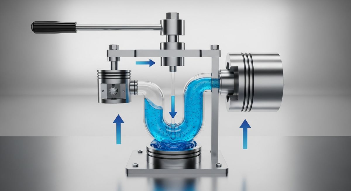
Many young engineers treat fluid systems as simple mechanical linkages. This is a dangerous mistake. Liquids do not behave like rigid steel rods; they distribute forces omnidirectionally. When you apply force to a confined fluid, that pressure does not just travel in the direction of the push—it attacks every square millimeter of the containment vessel with equal intensity. If your flanges, gaskets, or pipe walls are not rated to handle this uniform distribution, the system will fail at its weakest point.
Key Engineering Takeaways
- Fluid pressure is transmitted equally in all directions within a closed boundary.
- Mechanical advantage is achieved by scaling the surface area of the output piston relative to the input piston.
- Entrained air or gas pockets within a hydraulic fluid severely degrade system efficiency due to compressibility.
- Hydrostatic testing relies directly on this principle to verify the structural integrity of pressure vessels.
Complete Course on
Piping Engineering
Check Now
Key Features
- 125+ Hours Content
- 500+ Recorded Lectures
- 20+ Years Exp.
- Lifetime Access
Coverage
- Codes & Standards
- Layouts & Design
- Material Eng.
- Stress Analysis
What is Pascal’s Law in Engineering?
Pascal’s law: The physical rule dictating that static fluid pressure acts equally in all directions at any point within a confined fluid system. In industrial piping and hydraulics, this ensures that force applied at a small piston generates a proportionally larger force on a larger piston, enabling massive mechanical advantage.
To understand this on a molecular level, we must look at the behavior of incompressible fluids. Unlike gases, which have large intermolecular spaces that allow them to compress under load, liquids like mineral oils or water have tightly packed molecules. When you apply an external force to a confined liquid, the molecules cannot compress significantly. Instead, they transmit the kinetic energy directly to neighboring molecules. This energy transmission occurs at the speed of sound within that specific medium.
This omnidirectional pressure transmission is what makes hydraulics so powerful. In a closed piping system, the pressure at any given depth is uniform across a horizontal plane. If you increase the pressure at the inlet, that exact pressure increase registers instantly at every single point in the system, including the pipe walls, elbows, valves, and actuators.
Pascal’s Law Formula and Mathematical Derivation
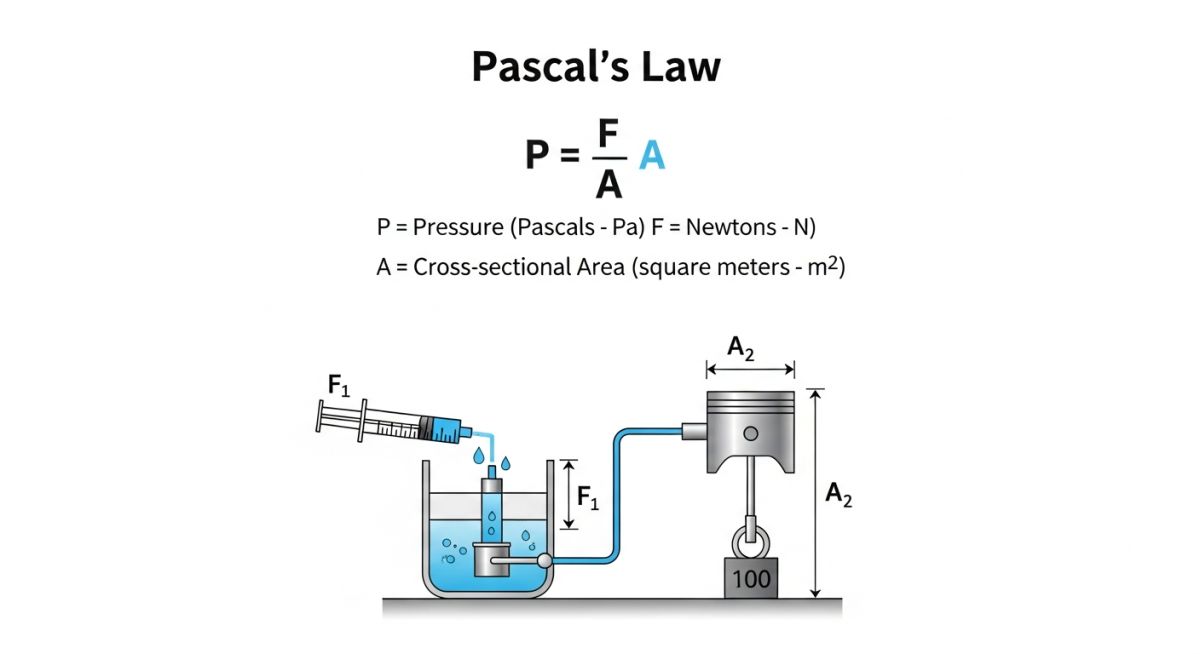
Pascal’s Law Formula: The mathematical expression represented as pressure equals force divided by area. In a closed hydraulic system with two interconnected pistons, this translates to the ratio of input force to input area being equal to the ratio of output force to output area, proving that output force scales directly with the area ratio.
Mathematically, we express this fundamental relationship as:
Where:
• P is the hydrostatic pressure (measured in Pascals or Newtons per square meter)
• F is the applied force (measured in Newtons)
• A is the cross-sectional area of the surface (measured in square meters)
In a dual-piston hydraulic system, because the pressure (P) remains constant throughout the continuous fluid path, we can set the pressure of the input side equal to the pressure of the output side:
This can be rearranged to solve for the output force (F2):
This simple equation reveals the secret of hydraulic power: by making the output area (A2) significantly larger than the input area (A1), we can multiply the input force (F1) by an enormous factor.
Step-by-Step Engineering Calculation Example
Let us calculate the output force and system pressure for an industrial hydraulic lift with the following design parameters:
- Input Piston Diameter (d1) = 50 mm (0.05 meters)
- Output Piston Diameter (d2) = 250 mm (0.25 meters)
- Input Force (F1) = 1,000 Newtons (approximately 100 kg of force)
Step 1: Calculate the cross-sectional area of both pistons
A1 = π * (d1 / 2)^2 = π * (0.025)^2 ≈ 0.001963 m^2
A2 = π * (d2 / 2)^2 = π * (0.125)^2 ≈ 0.049087 m^2
Step 2: Calculate the Area Ratio (Mechanical Advantage)
Area Ratio = A2 / A1 = 0.049087 / 0.001963 ≈ 25.01
Step 3: Calculate the Output Force (F2)
F2 = F1 * (A2 / A1) = 1,000 N * 25.01 = 25,010 Newtons (25.01 kN)
Step 4: Calculate the System Operating Pressure (P)
P = F1 / A1 = 1,000 / 0.001963 ≈ 509,424 Pascals
P ≈ 5.09 bar (or 73.8 PSI)
In this scenario, a modest input force of 1,000 N successfully lifts a load of over 25,000 N. However, physics always demands a trade-off. Because energy must be conserved, the distance the input piston travels is much greater than the distance the output piston moves. The volume of fluid displaced by the input piston must equal the volume received by the output piston:
Where s1 is the stroke length of the input piston and s2 is the stroke length of the output piston. In our example, to move the heavy output piston upward by 10 mm, the input piston must be stroked down by 250 mm.
In actual field operations, if your hydraulic fluid contains entrained air or gas bubbles, Pascal’s law is compromised. Air is highly compressible. When force is applied, the energy is spent compressing the air pockets rather than transmitting pressure to the output piston. This leads to spongy controls, erratic actuator movement, and localized overheating due to rapid bubble compression (adiabatic shearing), which can destroy cylinder seals and cause catastrophic system failure.
Selecting the correct hydraulic fluid is vital for maintaining the incompressibility required to satisfy Pascal’s law. The table below outlines the physical properties of common industrial fluids and their corresponding design standards.
This matrix maps the core physical parameters of Pascal’s law to their corresponding engineering applications and governing design codes.
| Parameter / Entity | Symbol | SI Unit | Practical Engineering Application | Governing Standard |
|---|---|---|---|---|
| Fluid Pressure | P | Pascal (Pa) / bar | System pressure rating, flange class selection | ASME B16.5 |
| Force | F | Newton (N) | Actuator output, pipe support structural loading | ASME B31.3 |
| Piston Area | A | Square Meter (m²) | Cylinder sizing, mechanical advantage design | ISO 6020 |
| Bulk Modulus | K / β | Gigapascal (GPa) | Fluid compressibility, water hammer calculations | ASTM D4177 |
| Hydrostatic Test Pressure | Pt | Pascal (Pa) / bar | Piping system integrity verification (1.5x design pressure) | ASME B31.3 Sec 345.4 |
Field Verification of Hydraulic Systems
Hydraulic system verification: The systematic process of inspecting, bleeding, and pressure-testing fluid power systems to ensure leak-free operation. This protocol guarantees that Pascal’s law operates efficiently without energy losses from air pockets or fluid bypass.
Before powering up any high-pressure hydraulic system, I always enforce a strict pre-commissioning checklist. Skipping these steps can lead to catastrophic seal blowouts, piping misalignment, or severe injury due to high-velocity fluid injection.
Site Verification Checkpoints
-
Verify Fluid Cleanliness: Ensure the hydraulic oil meets or exceeds ISO 4406 cleanliness codes (typically 16/14/11 for high-pressure systems) to prevent particulate wear on cylinder walls.
-
Perform High-Point Bleeding: Open all high-point bleed valves to purge trapped air. Trapped air compromises fluid incompressibility and dampens the pressure transmission.
-
Calibrate Pressure Gauges: Ensure all system pressure gauges are calibrated in accordance with ASME B40.100.
-
Inspect Seal Compatibility: Confirm that all cylinder and valve seals are chemically compatible with the specific hydraulic fluid (e.g., Viton seals for phosphate esters).
-
Check Torque on Flange Bolts: Verify that all flange connections are torqued to the specified values using a calibrated torque wrench to prevent high-pressure leaks.
Field Case Study: Real-World Application
The Problem: Loss of Tonnage in a 500-Ton Forging Press
During a commissioning project at a heavy manufacturing plant, a newly installed 500-ton hydraulic forging press failed to reach its rated output force. The system pressure gauge at the pump outlet registered the maximum design pressure of 315 bar, yet the main cylinder could only generate approximately 380 tons of force. The operations team suspected a faulty pump, which would have cost 45,000 to replace and delayed the project by three weeks.
The Diagnostic & Outcome
Instead of replacing the pump, I performed a systematic pressure-drop analysis across the system. By applying Pascal’s law, I knew that if the fluid was truly static and confined, the pressure should be identical throughout the circuit. However, we discovered a 45-bar pressure drop between the control valve manifold and the main cylinder inlet during the stroke.
The culprit was twofold: a severe internal bypass leak across the main piston seals and a massive pocket of trapped air in the upper dome of the cylinder. The air pocket was absorbing the initial fluid volume, while the degraded seals allowed fluid to slip from the high-pressure side to the return line, preventing the pressure from acting fully on the large piston area.
We replaced the damaged polyurethane seals with high-performance PTFE-energized seals and executed a thorough high-point air-bleeding procedure. Upon restarting, the press achieved its full 500-ton rating at a system pressure of only 295 bar. This simple application of fluid mechanics saved the client 120,000 in downtime and unnecessary equipment replacement.
This case study highlights a vital field reality: when troubleshooting hydraulic systems, always verify fluid integrity and containment boundaries before blaming the prime mover. Pascal’s law is absolute, but it requires a perfectly sealed, air-free environment to function.
Frequently Asked Engineering Questions
Here are the answers to some of the most common technical questions regarding the application of Pascal’s law in industrial piping and hydraulic design.
How does air entrainment affect Pascal’s law in hydraulic systems?
What is the difference between Pascal’s law and Bernoulli’s principle?
How does temperature affect pressure transmission in a closed system?
Why is water rarely used as the working fluid in industrial hydraulics?
How does pipe wall flexibility impact Pascal’s law calculations?
What ASME standards govern the design of high-pressure hydraulic piping?
===

📚 Recommended Resources: Pascal\'s law
Read these Guides
Related posts:
![Cross-section diagram showing a steel solar pile foundation embedded in layered soil profiles for structural analysis.]()
Essential Geotechnical Pile Design Data for Utility-Scale Solar Structures
![Professional surveyor conducting Topographical Surveys for Solar Projects on a large-scale utility site with complex terrain.]()
Topographical Surveys for Solar Projects: A Technical Engineering Guide
![A geotechnical drill rig performing soil sampling on a large, open field intended for a utility-scale solar farm project.]()
Geotechnical Investigation for Solar Farms: Essential Site Design Guide
![Isometric site plan showing Utility Corridor Planning for Data Centres with color-coded power, water, and telecom infrastructure paths.]()
Utility Corridor Planning for Data Centres: A Strategic Engineering Guide
![Aerial view of a data centre site showcasing perimeter drainage systems, detention basins, and site grading for flood prevention.]()
Drainage Design Considerations for Data Centres: A Technical Guide
![Professional surveyor using a Total Station on a large data centre construction site for topographical mapping.]()
Topographical Surveys for Data Centre Projects: A Technical Guide