What is an Oxidation-Reduction Potential (ORP)? How is it Measured?
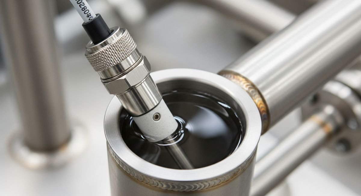
In my two decades of managing complex piping systems, I have found that Oxidation-Reduction Potential (ORP) is often the most misunderstood parameter in water chemistry. While pH tells us the concentration of hydrogen ions, ORP provides a direct window into the net oxidizing or reducing power of the fluid. Whether you are managing cooling tower biocides or monitoring wastewater effluent, understanding the electron transfer potential is non-negotiable for system longevity.
I have seen countless systems suffer from premature corrosion or biological fouling simply because the ORP setpoints were misaligned with the specific metallurgy of the piping. This guide breaks down the physics of the Nernst equation, the nuances of platinum electrode maintenance, and the practical realities of field-based electrochemical monitoring.
Key Takeaways for Engineers:
- ORP is measured in millivolts (mV) and is independent of pH, though highly sensitive to it.
- Platinum electrodes act as inert electron collectors, facilitating the potential measurement without participating in the reaction.
- Calibration requires standard buffer solutions with known millivolt values, typically quinhydrone or Zobell solutions.
- System grounding is the most common source of signal noise in industrial ORP installations.
Understanding Oxidation-Reduction Potential (ORP) Physics
ORP measurement relies on the Nernst equation, which defines the relationship between the potential of an electrochemical cell and the concentrations of the species involved. In an industrial setting, we use an inert platinum electrode to measure the potential difference between the process fluid and a stable reference electrode, typically silver/silver chloride (Ag/AgCl).
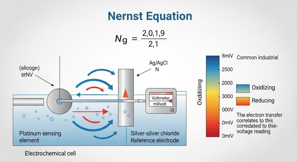
The Nernst equation is expressed as E = E0 + (RT/nF) * ln(Ox/Red), where E is the measured potential, E0 is the standard potential, R is the gas constant, T is absolute temperature, n is the number of electrons transferred, and F is Faraday’s constant. In practice, the sensor acts as a voltmeter, detecting the electron pressure of the solution. If the solution is oxidizing, it pulls electrons from the platinum surface, creating a positive potential. If it is reducing, it donates electrons, creating a negative potential.
Field Warning: The pH Dependency
ORP is inherently pH-dependent. Because many oxidation-reduction reactions involve hydrogen ions, a shift in pH will shift the ORP reading even if the concentration of the oxidant remains constant. Always normalize your ORP data against the system pH to avoid false alarms in your process control logic.
When designing the installation, I prioritize the placement of the sensor. It must be located in a high-turbulence zone to ensure representative sampling, but away from direct chemical injection points. If the sensor is too close to a chlorine or ozone injection quill, the localized concentration will cause erratic readings and premature sensor degradation. I recommend a minimum of 10 pipe diameters downstream of any chemical injection point.
Calibration is the heartbeat of reliable ORP monitoring. Unlike pH, which uses multiple buffers, ORP calibration is often a single-point check. I utilize quinhydrone solutions for their stability at specific pH levels. If the sensor deviates by more than 20mV from the theoretical value, the platinum tip likely requires cleaning or the reference junction is fouled. In high-fouling environments, such as raw water intake or secondary wastewater, I specify sensors with self-cleaning ultrasonic heads to prevent biofilm accumulation on the platinum surface.
Electrochemical Monitoring Trade-offs: A balanced assessment of ORP implementation for real-time process control and system integrity.
Advantages
- Provides a single, comprehensive value for the total oxidizing/reducing capacity of a solution.
- Enables automated, real-time control of chemical dosing, reducing waste and chemical costs.
- Highly effective for monitoring the efficacy of biocides in cooling water and disinfection in potable water.
- Low maintenance requirements compared to complex analytical instruments like gas chromatographs.
- Rapid response time to changes in process chemistry, allowing for immediate corrective action.
Disadvantages
- Readings are highly sensitive to pH fluctuations, requiring complex compensation algorithms.
- Platinum electrodes are susceptible to “poisoning” by sulfides or heavy metals, leading to drift.
- Does not distinguish between specific chemical species (e.g., free chlorine vs. combined chlorine).
- Requires frequent calibration in high-temperature or high-pressure industrial environments.
- Signal interference from stray currents in large-scale industrial piping networks is common.
Industrial Process Integration: Practical deployment of ORP sensors across diverse chemical and environmental engineering sectors.
Cooling Tower Biocide Management
ORP is the industry standard for controlling oxidizing biocides like chlorine or bromine in cooling water loops. By maintaining a specific mV setpoint, the system ensures sufficient residual to prevent Legionella growth while minimizing the corrosive impact of over-chlorination on carbon steel piping components.
Wastewater Cyanide Destruction
In metal finishing plants, ORP is used to monitor the alkaline chlorination process for cyanide destruction. The system triggers the addition of sodium hypochlorite until the ORP reaches a specific threshold, ensuring the complete oxidation of toxic cyanide to harmless cyanate and nitrogen gas.
Chromium Reduction Processes
Hexavalent chromium reduction requires a precise reducing environment, typically achieved by adding sodium metabisulfite. ORP sensors monitor the drop in potential to confirm that the chromium has been successfully reduced to the less toxic trivalent state before the effluent enters the secondary treatment stage.
Potable Water Disinfection
Municipal water treatment facilities utilize ORP as a surrogate for monitoring the disinfection potential of ozone or chlorine dioxide. This provides a more accurate reflection of the water’s ability to neutralize pathogens compared to simple residual concentration measurements, which can be masked by organic demand.
In industrial water treatment, selecting the correct electrode material is as critical as the calibration frequency itself. The following table outlines the standard performance metrics and material compatibility for common ORP sensing elements used in harsh chemical environments. These values assume adherence to ASTM D1498 standards for measuring oxidation-reduction potential in water.
Engineers must evaluate the chemical compatibility of the reference junction and the sensing element against the process stream’s specific contaminants. Failure to account for poisoning agents, such as sulfides or heavy metals, will lead to significant drift and inaccurate process control loops. Always verify the manufacturer’s specifications against your site’s specific chemical profile before installation.
| Electrode Material | Typical Range (mV) | Primary Application | Maintenance Interval |
|---|---|---|---|
| Platinum (Pt) | -1500 to +1500 | General Oxidizing/Reducing | Monthly |
| Gold (Au) | -1000 to +1000 | Cyanide/High Sulfide | Bi-Weekly |
| Silver (Ag) | -500 to +500 | Halide Monitoring | Quarterly |
The following matrix maps the core electro-chemical entities to their respective physical parameters and governing standards. This mapping is essential for instrumentation engineers tasked with integrating ORP sensors into Distributed Control Systems (DCS) or Programmable Logic Controllers (PLC). Understanding these relationships ensures that the signal conditioning and data interpretation remain consistent across the entire plant infrastructure.
By aligning these technical entities with the appropriate ISA and IEC standards, you minimize the risk of signal noise and measurement bias. Note that the “Signal Type” column refers to the standard output expected by modern industrial transmitters, which typically require high-impedance inputs to prevent loading the electrochemical cell.
| Entity | Parameter | Standard Reference |
|---|---|---|
| Nernst Potential | Voltage (mV) | ASTM D1498 |
| Reference Electrode | Stability (mV/hr) | IEC 60746-2 |
| Transmitter Output | 4-20 mA / HART | ISA-5.1 |
ORP System Verification: A systematic approach to validating the integrity of your oxidation-reduction potential measurement loop is required to ensure process safety and compliance with environmental discharge regulations. This checklist covers the essential steps for field verification, from initial sensor installation to final loop calibration.
- ☐ Sensor Inspection: Verify the platinum or gold sensing element is free of physical damage, scratches, or chemical coatings that could impede ion exchange.
- ☐ Junction Integrity: Inspect the reference junction for clogging or crystallization; ensure the electrolyte level is sufficient for the expected service life.
- ☐ Calibration Buffer Check: Use fresh, NIST-traceable ORP buffer solutions (typically 200mV or 475mV) to verify the transmitter’s slope and offset.
- ☐ Loop Impedance Test: Confirm that the cable shielding is properly grounded at the transmitter end to prevent electromagnetic interference (EMI) from affecting the high-impedance signal.
- ☐ Temperature Compensation: Ensure the integrated temperature sensor (RTD) is calibrated, as the Nernst equation is inherently temperature-dependent.
- ☐ DCS Signal Validation: Perform a loop check to confirm that the 4-20 mA signal at the transmitter matches the value displayed in the control room.
Regular site verification is not merely a maintenance task; it is a fundamental requirement for maintaining the accuracy of chemical dosing systems. If your readings deviate by more than 10mV during a standard buffer check, the electrode must be cleaned or replaced immediately. Always document these checks in your maintenance management system to satisfy regulatory audit requirements.
Problem: Chronic ORP Drift in Wastewater Treatment
A chemical processing facility reported erratic ORP readings in their effluent neutralization tank, leading to inconsistent chlorine dosing and potential environmental non-compliance.
- Accumulation of organic biofilms on the platinum sensing surface.
- Reference junction poisoning due to high sulfide concentrations in the influent.
- Inadequate grounding of the signal cable causing 60Hz noise interference.
- Failure to perform routine calibration against standard buffer solutions.
Outcome: Restored Control and Compliance
Following a comprehensive system overhaul, the facility achieved stable, repeatable ORP measurements and optimized chemical consumption.
- Implemented a weekly automated cleaning cycle using a mild acid wash.
- Switched to a double-junction reference electrode to prevent sulfide poisoning.
- Installed a dedicated signal isolator to eliminate ground loop noise.
- Reduced chemical reagent waste by 15% through tighter control loop tuning.
My recommendation for similar industrial applications is to prioritize the selection of the reference electrode junction type. In environments with high concentrations of sulfides or heavy metals, a standard single-junction probe will inevitably fail. Investing in a robust, application-specific sensor design at the outset will save significant operational costs and prevent the headaches associated with chronic measurement drift.
How does temperature affect ORP readings?
- Most modern ORP transmitters include automatic temperature compensation (ATC) to normalize readings to a reference temperature, typically 25 degrees Celsius.
- Without proper compensation, a temperature swing of 10 degrees can introduce significant errors in the millivolt reading, potentially triggering false alarms or incorrect chemical dosing.
- Always ensure the integrated temperature sensor is properly submerged and calibrated to avoid skewed data.
What causes ORP sensor poisoning?
- Sulfides are the most common culprits, reacting with silver-based reference electrodes to form silver sulfide, which clogs the junction and alters the reference potential.
- Heavy metals can plate out onto the platinum sensing surface, effectively masking the true oxidation-reduction potential of the bulk solution.
- Using double-junction electrodes or pressurized reference systems can significantly mitigate these effects by creating a physical barrier against contaminant ingress.
Can I use pH buffers to calibrate ORP?
- ORP calibration requires solutions like Quinhydrone or Zobell’s solution, which provide a precise millivolt output at a given temperature.
- Using a pH buffer will not provide the necessary redox potential, and it may even contaminate the reference junction of the ORP probe.
- Always follow the manufacturer’s recommendations for calibration standards to ensure compliance with ASTM D1498.
Why is high impedance required for ORP?
- Transmitters must have an input impedance of at least 10 to 100 megaohms to ensure the measured potential is not “loaded” by the instrument.
- This high-impedance requirement also makes the signal susceptible to electromagnetic interference, necessitating the use of high-quality shielded cables.
- Proper grounding of the cable shield is essential to maintain the integrity of this sensitive, low-current signal path.
How often should I clean the electrode?
- Signs that cleaning is required include slow response times, erratic readings, or a failure to reach the expected potential in a buffer solution.
- Use only manufacturer-recommended cleaning agents, such as mild acids or specialized surfactants, to avoid damaging the sensing element.
- Automated cleaning systems, such as air-blast or ultrasonic cleaners, can be installed to maintain sensor performance in high-fouling environments.
What is the role of the reference electrode?
- Most reference electrodes use a silver/silver-chloride (Ag/AgCl) system, which maintains a fixed potential as long as the internal electrolyte concentration remains stable.
- The junction between the reference electrode and the process fluid must allow for ion exchange while preventing the bulk fluid from contaminating the internal electrolyte.
- If the reference junction becomes clogged or depleted, the reference potential will drift, leading to inaccurate and unreliable ORP measurements.
📚 Recommended Resources: Oxidation
Read these Guides
- 📄 Oxidation State of Nickel: Chemistry & Engineering Guide (2026)
- 📄 Carbon Monoxide Poisoning Prevention: Industrial Safety and Engineering Controls
- 📄 Understanding Common Forms of Corrosion: Corrosion Types in Piping Systems
- 📄 Oil Mist Lubrication System Design and Reliability Engineering Best Practices
Complete Course on
Piping Engineering
Check Now
Key Features
- 125+ Hours Content
- 500+ Recorded Lectures
- 20+ Years Exp.
- Lifetime Access
Coverage
- Codes & Standards
- Layouts & Design
- Material Eng.
- Stress Analysis
