OISD 118: Layouts for Oil and Gas Installations (2026 Guide)
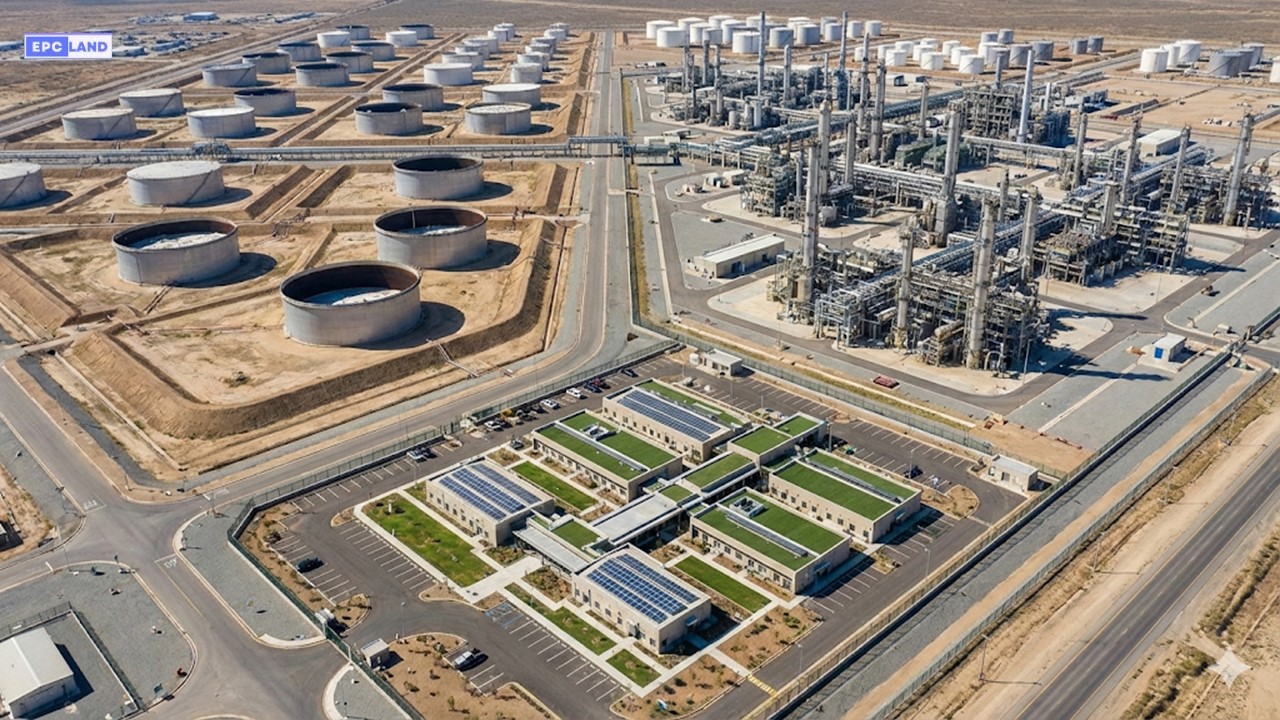
The OISD 118 standard is the definitive governing code for the layout, design, and safety spacing of petroleum installations in India. Whether you are designing a Greenfield refinery or executing a brownfield expansion, adherence to these “Layouts for Oil and Gas Installations” is not just a regulatory formality—it is the primary engineering safeguard against catastrophic escalation during fire incidents.
In 2026, the focus on OISD 118 latest revision 2026 compliance has intensified, particularly regarding the separation distances between hazardous units and the optimization of land use. This guide breaks down the complex tabular data into actionable engineering logic, ensuring your site master plan passes strict safety audits.
What is OISD 118?
OISD 118 is a safety standard issued by the Oil Industry Safety Directorate (OISD) that defines the mandatory minimum inter-distances (spacing) between storage tanks, process units, and boundary walls. Its primary objective is to prevent the escalation of fire from one facility to another and ensure safe access for firefighting operations.
⚡ Quick Navigation
🧠 Test Your OISD Knowledge
Complete Course on
Piping Engineering
Check Now
Key Features
- 125+ Hours Content
- 500+ Recorded Lectures
- 20+ Years Exp.
- Lifetime Access
Coverage
- Codes & Standards
- Layouts & Design
- Material Eng.
- Stress Analysis
Scope of OISD 118: 2026 Applicability
The scope of OISD 118 Refinery Layout Compliance encompasses the safety aspects of plant design and layout for oil and gas facilities. The primary objective is to minimize the risks associated with fire, explosion, and toxic releases, while optimizing the use of space and resources. In 2026, this standard remains the cornerstone for achieving PESO (Petroleum and Explosives Safety Organization) certification across the Indian hydrocarbon sector.
Downstream Assets
- Petroleum Refineries
- Lube Oil Installations
- Aviation Storage & Fueling Stations
Midstream & Upstream
- Oil / Gas Production & Processing
- Pipeline Terminals & Installations
- Crude Oil Gathering Stations
Specialized Storage
The standard specifically addresses LPG mounded storage spacing and tank farm spacing table requirements for:
- LPG Facilities
- Marketing Depots & Terminals
EPCLand YouTube Channel
2,500+ Videos • Daily Updates
Fundamental Plant Layout Philosophy
The 2026 engineering approach to OISD 118 Refinery Layout Compliance is governed by a structured philosophy designed to isolate hazards and streamline emergency response. By adhering to these core principles, facilities ensure that a localized incident does not escalate into a site-wide disaster.
Block Layout & Separation
Facilities are arranged by material flow. Process unit inter-distance norms dictate that units and dyked storage enclosures must reside in separate blocks, bordered by perimeter roads that serve as vital firebreaks.
Traffic & Access
Main traffic arteries are positioned outside hazardous zones. Layouts prioritize separate access for personnel and materials, ensuring roads can accommodate the largest firefighting apparatus for 2026 emergency standards.
Risk & Wind Orientation
Heaters and the flare stack sterile zone radius are oriented based on prevailing wind directions to prevent flammable vapor drift toward ignition sources or the green belt buffer zone width.
Accessibility & Growth
Every blast resistant control room OISD compliant design must allow for maintenance accessibility and future expansion flexibility without compromising the original safety integrity levels.
Key Regulatory Definitions
- Process Unit
- A specific arrangement of equipment dedicated to refining or gas processing operations.
- Block
- A designated area containing one or more units, typically surrounded by primary roads.
- Safety Distance
- The mandatory separation required to minimize risks using a tank farm spacing table.
- Utility Station
- Centralized hubs providing essential water, air, steam, and power to the processing blocks.
“In 2026, the philosophy of OISD 118 transcends mere compliance; it is a commitment to ensuring that the safety of personnel and the environment is paramount through rigorous separation and strategic orientation.”
The Science of Separation: OISD 118 Layout Requirements
The fundamental physics behind OISD 118 Layout Requirements revolves around thermal radiation management. In 2026, engineering designers prioritize the “Block Layout Philosophy,” where hazardous equipment is grouped into distinct islands. This approach ensures that inter-distance safety norms are maintained to prevent a fire in one area from exceeding the 12.5 kW/m2 radiation threshold at the boundary of the next block.
Fluid Risk Categorization
Spacing cannot be determined without first analyzing the Petroleum Class A B C classification. This hierarchy, based on flash points, dictates the severity of the “Sterile Zone” required around storage assets:
- Class A: Flash point below 23°C (e.g., Naphtha, Petrol). Requires maximum spacing.
- Class B: Flash point 23°C to 65°C (e.g., Kerosene, ATF).
- Class C: Flash point 65°C to 93°C (e.g., Diesel, LDO).
- Excluded: Flash point 93°C and above (e.g., Bitumen).
Engineering Insight: Safe Distance Calculation
While OISD provides fixed tables, the underlying safety distance (D) is often validated using thermal radiation modeling where:
Where I is Radiation Intensity, Q is Heat Release Rate, F is Fraction of radiation, and R is the Distance from the fire center.
Primary Inter-Distance Norms
The following data represents the tank farm spacing table logic for 2026 compliance. These distances are the absolute minimums required between various facility components.
| From / To Facility | Process Unit | Storage Tank (Class A) | Boundary Wall |
|---|---|---|---|
| Process Unit | 30m | 60m | 30m |
| Storage Tank (Class A) | 60m | 0.5D (Min 20m) | 30m |
| LPG Storage | 90m | 60m | 50m |
Special consideration is given to process unit inter-distance norms when dealing with multi-train refineries. By maintaining a 30m corridor, plant operators ensure that emergency vehicles can circulate even if one unit is engulfed in smoke or flame.
Plant Layout Philosophy: Core Principles
The philosophy of plant layout as per OISD 118 is not merely about aesthetics; it is a rigid framework designed to mitigate catastrophic risk. A compliant layout is built upon five non-negotiable pillars:
Safety First
Ensuring personnel and environmental safety by maintaining adequate separation distances to prevent fire escalation.
Accessibility
Guaranteeing clear access paths and fire lanes for emergency response vehicles and maintenance crews.
Flexibility
Designing layouts that allow for future expansion or modification without disrupting ongoing plant operations.
Minimizing Risk
Strategically locating hazardous facilities away from non-hazardous ones to isolate potential toxic or explosive releases.
Strict Compliance
Full adherence to national standards, specifically OISD 118, to ensure the facility meets statutory requirements.
Layout of Blocks and Facilities
The layout of blocks and facilities must achieve a delicate balance between safety, operational efficiency, and cost-effectiveness. Here are some key considerations as per OISD 118 for specific zones:
-
1
Process Blocks Units should be grouped by function and hazard potential. High-hazard units must be isolated from low-hazard areas and critical infrastructure.
-
2
Control Rooms Must be strategically placed to offer operators a clear view of process units while maintaining a safe distance (or using blast-resistant design) to ensure habitability during incidents.
-
3
Storage Areas Tanks for Crude, LPG, and other hydrocarbons must be in dedicated zones with strict OISD 118 safety distances from process blocks.
-
4
Utility Stations Located close enough to serve process units efficiently, yet distant enough to remain operational and undamaged if a unit failure occurs.
Layout of Process Units
The internal layout of process units is a critical aspect of plant design. As per OISD 118, specific guidelines regarding segregation must be followed. High-risk units handling flammable gases or toxic substances must be separated from lower-risk units to prevent the “Domino Effect.”
Additionally, the layout must incorporate fire barriers and blast walls between high-hazard units to minimize impact. The table below outlines the recommended separation distances for various process unit types:
| Process Unit Type | Recommended Separation Distance (Meters) |
|---|---|
| Flammable Gas Processing | 60 |
| Catalytic Cracking Unit (FCCU) | 50 |
| Crude Oil Distillation (CDU) | 45 |
| Storage Tanks (Adjacent) | 30 |
| Utility Stations | 25 |
* Note: These are baseline values. Always refer to specific tables in OISD 118 for adjustments based on Blast Resistant construction or fire-proofing measures.
Layout of Storage Tanks: Containment & Separation
Storage tanks represent the highest accumulated hydrocarbon inventory in any facility. Therefore, the layout of storage tanks under OISD 118 is governed by strict rules regarding containment (dykes) and separation to prevent pool fires from escalating into full-blown disasters.
Separation Distances
To prevent fire spread, the distance between two tanks must generally be at least 0.5 × (Diameter of larger tank). For specific scenarios, refer to OISD Tables 3, 4, and 5.
Tank Farm Layout
Tanks should be arranged in rows (max two rows) to allow firefighting access. Single rows are preferred if the aggregate capacity exceeds 50,000 cum.
Ventilation & Drainage
Proper grading is required to prevent vapor accumulation. Drainage systems must route spills away from tanks to remote impounding basins.
Bund Walls (Dykes)
Dykes are mandatory. The enclosure must hold the full volume of the largest tank. Dyke height must be between 1.0m and 2.0m.
Mandatory Critical Dyke Enclosure Rules
- Capacity Limits per Dyke: Maximum 60,000 cum for Fixed Roof tanks and 120,000 cum for Floating Roof tanks.
- No Process Equipment: Pumps, heaters, or process vessels are strictly prohibited inside the dyked area.
- Grouping: Tanks must be grouped by classification (Class A, B, C). Do not mix hazardous classes within a single bund without firewalls.
Layout of LPG Facilities: High Hazard Zones
Liquefied Petroleum Gas (LPG) poses a unique BLEVE risk. Consequently, the layout of LPG facilities demands distinct zones, segregated from standard petroleum handling. OISD 118 mandates that these facilities be located downwind of process units and away from other hydrocarbon sources.
⚠️ Critical Safety Measures for LPG
- Vessel Orientation: Horizontal vessel axes must not face vital areas, control rooms, or other vessels (to prevent “missile effect” during failure).
- Grouping Cap: Vessels must be grouped in clusters of max 6, with a total capacity cap of 15,000 cum per group.
- Group Separation: Minimum 30 meters distance between different groups of spheres or bullets.
- Spill Management: Remote spill sumps must be located at a distance of at least the vessel diameter or 15 meters (whichever is greater).
Handling & Logistics:
For bottling plants and bulk handling, OISD 118 requires LPG truck gantries to be in separate blocks. Rail loading gantries have strict restrictions on the number of wagons and maintained distances. Always consult Tables 6 and 7 of the standard for precise LPG separation distances.
Layout of Utility Stations
Utility stations (Power, Water, Steam, Air) are the lifeline of the plant. Per OISD 118, their layout focuses on survivability:
- Proximity vs. Safety: Located close enough for efficiency but outside the immediate blast zone of process units (Min 25m).
- Accessibility: Must have independent road access for maintenance and emergency isolation.
- Fire Safety: Equipped with independent hydrants and extinguishers, separate from the main process fire loop if necessary.
Table 2: Consolidated Separation Distances (Quick Reference)
| Facility Type | Minimum Separation Distance (Meters) |
|---|---|
| Process Units | 45.0 |
| Storage Tanks | 30.0 |
| LPG Facilities | 60.0 |
| Control Rooms | 50.0 |
| Utility Stations | 25.0 |
Why Compliance with OISD 118 is Non-Negotiable
🎓 Quiz: OISD 118 Compliance Check
Test your understanding of why these regulations matter.
Download OISD 118 PDF & Master the Code
Searching for the OISD 118 pdf often leads to outdated or fragmented links. Access the verified standard file and elevate your engineering career with our comprehensive training.
Critical Theory: Mastering OISD 118 Layout Rules
Designing a refinery or a massive tank farm requires more than just fitting equipment onto a plot plan. The OISD 118 standard establishes a grid-based approach to safety, dividing installations into separate “blocks” based on process risks. These petroleum installation layout rules are fundamentally derived from thermal radiation modeling and blast overpressure calculations.
The core philosophy rests on three pillars:
- Segregation: Keeping high-hazard potential sources (like Hydrocrackers) physically distant from administrative buildings or boundary walls.
- Containment: Ensuring that a spill in one block (dyke area) does not flow into another.
- Access: Guaranteeing two-sided access for fire tenders to every major process unit.
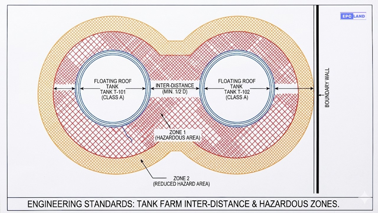
Inter-Distance Between Storage Tanks
The most frequently consulted section of the code involves the inter-distance between storage tanks. OISD 118 prescribes distances based on the tank diameter (D) and the classification of the product (Class A, B, or C).
For floating roof tanks storing Class A products (like Crude Oil), the spacing is critical to prevent “tank-to-tank” fire escalation. If a rim seal fire occurs, the radiant heat must not compromise the structural integrity of the adjacent tank shell. Furthermore, this spacing must align with hazardous area classification zones (Zone 0, 1, and 2) to ensure that electrical equipment installed nearby does not become a source of ignition for fugitive emissions.
Engineering Calculation: Tank Spacing
When calculating the Shell-to-Shell distance (S) between two Floating Roof Tanks designated for Class A products:
- S = Minimum Shell-to-Shell Distance (meters)
- D1 = Diameter of Tank 1 (meters)
- D2 = Diameter of Tank 2 (meters)
LPG Layouts: Mounded vs. Above Ground
Liquefied Petroleum Gas (LPG) presents a unique BLEVE (Boiling Liquid Expanding Vapor Explosion) hazard. Consequently, OISD 118 strongly incentivizes the use of mounded storage.
LPG mounded bullet spacing requirements are significantly more lenient than above-ground spheres because the earth cover provides thermal insulation against external fires and prevents the “domino effect.” While above-ground spheres might require a separation distance of 1.0 × Diameter, mounded bullets can often be spaced as close as 1.5 meters (skin-to-skin) to facilitate construction and maintenance, saving massive amounts of real estate in brownfield projects.
Table 1: General Separation Distances (Simplified OISD 118)
| From Facility | To Facility | Min. Distance (m) | Basis |
|---|---|---|---|
| Process Unit | Storage Tank (Class A) | 30.0 | Thermal Radiation |
| Process Unit | Control Room | 30.0 / 15.0 | Blast Pressure (15m if blast resistant) |
| Storage Tank | Boundary Wall | 20.0 | Public Safety |
| LPG Storage | Process Unit | 45.0 | High Hazard Separation |
| Fire Water Pump | Hazardous Area | 60.0 | Utility Integrity |
* Note: Distances are indicative. Always refer to the specific OISD 118 Table corresponding to your facility type (Refinery vs. Marketing Terminal).
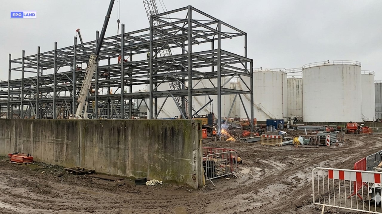
Case Study: OISD 118 Compliance in Brownfield Expansion
Project Scope
New Hydrocracker Unit (HCU) Integration
Site Constraint
Adjacent to Class A Naphtha Storage
Key Hazard
High Pressure Hydrogen + Volatile Storage
Outcome
100% OISD Compliant Commissioning
The Challenge: The “Impossible” Plot Plan
In a recent brownfield expansion for a major refinery in Western India, the client required the installation of a 2.5 MMTPA Hydrocracker Unit (HCU). The only available land was a narrow strip sandwiched between an existing Naphtha Tank Farm (Class A) and the main Power Plant. Initial feasibility studies suggested the project was non-viable because standard OISD 118 spacing rules required a minimum of 45 meters between the high-pressure reaction section and the storage tanks.
Engineering Analysis & Mitigation
The EPC team conducted a granular layout optimization. While the reactor section posed the highest risk, the fractionation section of the HCU was classified as a lower hazard. By splitting the unit layout and placing the fractionation columns closer to the tank farm (adhering to the 30-meter rule for process units) and pushing the reactors to the far side, the team created a stepped safety zone.
However, a critical bottleneck remained: the existing fire water headers were running directly through the proposed blast zone. According to the fire water network design OISD requirements (OISD 116/118), the fire water network must remain operable even during a catastrophic event.
The Solution: Loop Re-Routing & Blast Walls
The engineering solution involved three distinct moves:
- Network Upgrade: The underground fire water ring main was re-routed outside the 15-meter blast contour of the new unit, upgrading the pipe diameter from 16″ to 24″ to handle the increased hydraulic demand of the HCU deluge systems.
- Blast Resistant Control: Since the satellite control room could not be moved to the required 30 meters, it was designed as a Blast Resistant Module (BRM), permitting a reduced separation distance of 15 meters as per the specific proviso in OISD 118.
- Vertical Expansion: To conserve ground space, air coolers were mounted on top of the pipe rack, a design choice that required strict vibration analysis but cleared ground access for the mandatory 4.5-meter wide fire tender roads.
✅ Project Result
The facility passed the pre-commissioning safety audit (PCSA) with zero major observations. The layout optimization saved the client approximately $4.2 Million in land acquisition costs while maintaining full adherence to the statutory safety distances.
Frequently Asked Questions (OISD 118)
What is the difference between OISD 118 and OISD 244?
OISD 118 specifically covers “Layouts for Oil and Gas Installations,” focusing on refineries, processing plants, and major tank farms. In contrast, OISD 244 deals with the storage and handling of petroleum products at smaller depots and terminals. Always check the facility classification before selecting the governing standard.
Can we reduce the separation distance by using a Fire Wall?
Generally, OISD 118 is strict about clear distances. However, specific clauses allow for reduced spacing (e.g., between a control room and a process unit) if a certified blast-resistant wall or building is utilized. Note that for storage tanks, fire walls do not typically allow for a reduction in the mandatory shell-to-shell spacing.
Does OISD 118 apply to existing brownfield installations?
Yes. While older installations may have been built under previous revisions, major modifications or expansions (like the one in our Case Study) trigger the requirement to comply with the OISD 118 latest revision 2026. If compliance is physically impossible, a rigorous Quantitative Risk Assessment (QRA) and OISD steering committee approval are usually required.
How is the capacity of a Dyke Area calculated?
The dyke (bund) enclosure must be able to contain the entire contents of the largest single tank in that group, plus an allowance for freeboard (typically 200mm) to prevent overtopping during foam application or rain accumulation.
Conclusion: Safety by Design
The guidelines within OISD 118 are written in the ink of past industry lessons. Whether you are calculating inter-distance between storage tanks or plotting the location of a new control room, adherence to this standard is the first line of defense against disaster. As we move through 2026, integrating these static layout rules with dynamic fire water network designs ensures that our petroleum installations remain safe, compliant, and operational.
Visit Official OISD Portal© 2026 Epcland Engineering. All rights reserved.
Additional Resources on OISD 118
Expand your knowledge on OISD 118 layout rules, brownfield upgrades, and fire safety compliance with these specialized engineering guides:
Refinery Safety Distances
Deep dive into specific spacing metrics.
Refinery Layout Compliance
Step-by-step compliance checklist.
Layout Requirements
Detailed breakdown of statutory requirements.
EPC Compliance Quiz
Test your team’s OISD knowledge.
Fire Water Compliance
Challenges in brownfield & aging plants.
CDU Upgrade Case Study
Real-world upgrade compliance.

Related posts:
![High-grade industrial Wing Nut Types and Applications for mechanical assemblies.]()
Wing Nut Types and Applications: The 2026 Engineering Guide
![Industrial Monorail Crane Systems installed in a modern manufacturing plant 2026.]()
Monorail Crane Systems: Design, Types & 2026 Standards Guide
![Lead engineer performing a Factory Acceptance Test FAT on an industrial skid system 2026]()
Factory Acceptance Test FAT: The 2026 Engineering Guide to Zero-Defect Delivery
![Professional engineering workspace showing a Basis of Design document layout for a 2026 project.]()
Basis of Design: How to Write a BOD for Engineering Projects in 2026
![Industrial Flare Knockout Drum Sizing and installation in a refinery relief system.]()
Flare Knockout Drum Sizing: Design & API 521 Standards (2026 Guide)
![Advanced Reboiler Control Systems in a modern petrochemical refinery 2026.]()
Reboiler Control Systems: Engineering Guide to Precision Control 2026


