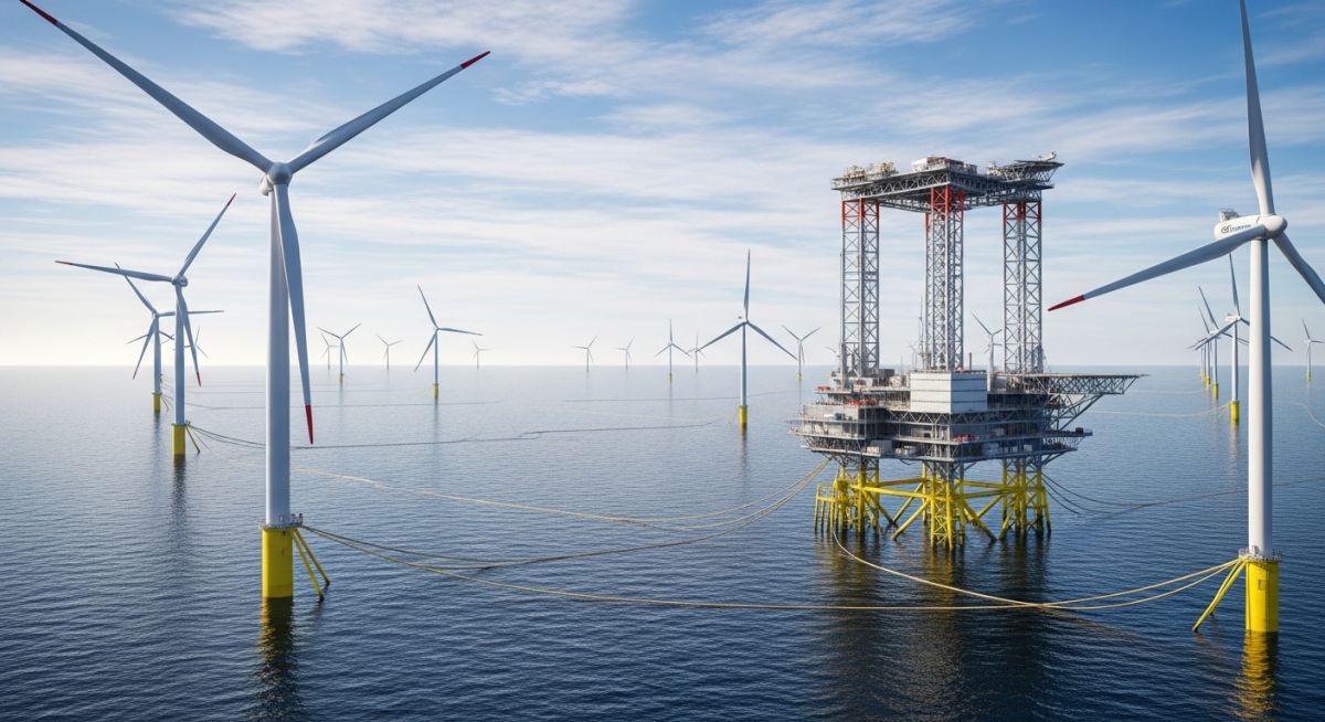
Offshore Wind Farm Engineering: Foundations and Grid Integration
In my two decades of experience navigating complex energy infrastructure, I have observed that offshore wind represents the most rigorous challenge for mechanical and structural engineers. Unlike onshore projects, offshore wind farm engineering requires balancing extreme hydrodynamic loading, corrosive saline environments, and the logistical nightmare of deep-water installation.
We are no longer just building turbines; we are constructing massive, interconnected power plants in the middle of the ocean. This guide dissects the transition from fixed-bottom foundations to floating platforms and the critical electrical infrastructure required to bring that power to the grid.
Key Engineering Takeaways:
- Understanding the transition from monopile to jacket and floating foundation types.
- Navigating the ASME and API standards for marine structural steel.
- Mitigating corrosion through advanced cathodic protection and coating systems.
- Optimizing subsea cable routing to minimize mechanical fatigue and thermal degradation.
Offshore Wind Farm Engineering: Structural Design Principles
Offshore Wind Farm Engineering: The application of fluid-structure interaction analysis and geotechnical modeling to ensure turbine stability under cyclic wave and wind loading conditions.
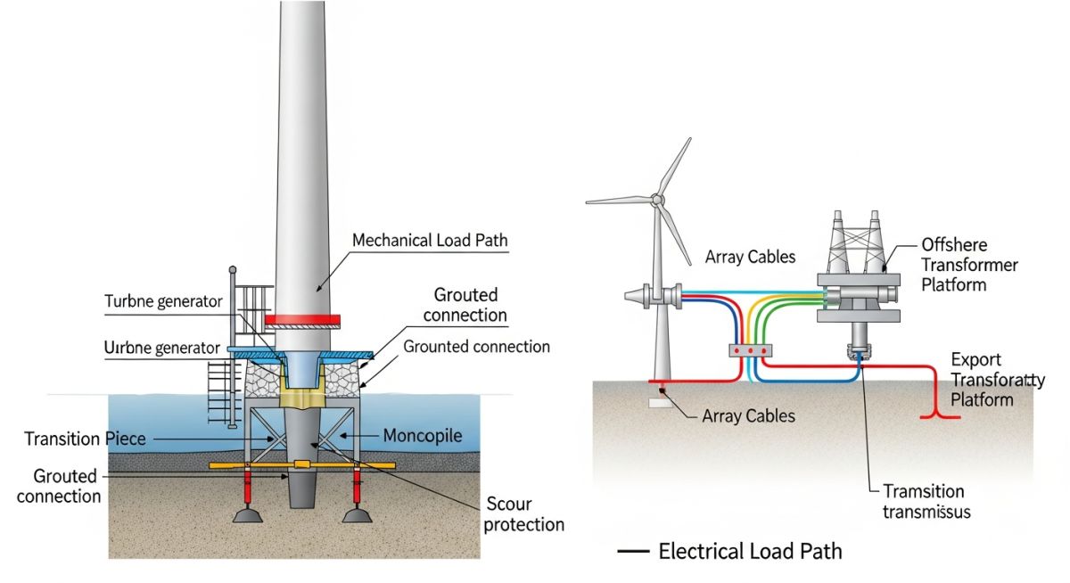
The structural design of an offshore wind turbine is a masterclass in fatigue management. We must account for the primary load path: wind-induced thrust on the rotor, transferred through the tower, and resisted by the foundation. In shallow waters (up to 50 meters), monopiles remain the industry standard. However, as we move into deeper waters, the design shifts toward jacket structures or floating semi-submersibles.
Foundation Load Calculations
When calculating the overturning moment, we utilize the Morison equation for wave loading, which combines inertia and drag forces. The total force F is defined as the sum of the inertia force and the drag force acting on the submerged cylinder. For a monopile, the bending moment at the mudline is the critical design parameter.
Critical Design Parameters:
- Natural Frequency: Must be tuned to avoid the 1P (rotor frequency) and 3P (blade passing frequency) ranges to prevent resonance.
- Soil-Structure Interaction: Utilizing P-Y curves to model the lateral soil resistance against the pile.
- Corrosion Allowance: Typically 3-6mm added to the wall thickness, supplemented by sacrificial anodes or Impressed Current Cathodic Protection (ICCP).
Field Warning: Fatigue Life Assessment
In my experience, the most common failure point is the weld connection between the transition piece and the monopile. High-cycle fatigue, driven by millions of wave cycles, requires rigorous spectral fatigue analysis. Always verify that your weld profiles meet AWS D1.1 or ISO 19902 standards for offshore structures.
Floating wind turbines introduce a new set of variables, specifically hydrostatic stability and mooring line tension. We use catenary or taut-leg mooring systems to maintain position. The design must ensure that the platform’s pitch and roll motions do not exceed the operational limits of the turbine’s pitch control system, which typically triggers a shutdown if the tilt exceeds 10 degrees.
Offshore Wind Infrastructure: A comparative analysis of the technical and economic trade-offs inherent in deploying large-scale wind energy assets in marine environments.
Technical Advantages
- Higher capacity factors due to more consistent and stronger offshore wind speeds.
- Reduced visual and noise impact on coastal populations, allowing for larger turbine arrays.
- Ability to transport massive components via sea, bypassing road infrastructure constraints.
- Lower turbulence intensity compared to onshore sites, extending component fatigue life.
Technical Disadvantages
- Extreme corrosive environment requiring specialized marine-grade coatings and maintenance.
- High logistical complexity for installation and subsea cable repair operations.
- Significant geotechnical uncertainty in deep-water seabed conditions.
- Complex electrical grid integration requiring long-distance HVDC transmission systems.
Offshore Energy Deployment: Strategic implementation of wind technology across diverse industrial and regional power sectors to meet decarbonization targets.
Grid-Scale Power Generation
Large-scale offshore wind farms are primarily deployed to replace aging coal and gas-fired baseload power plants. These projects utilize high-voltage alternating current (HVAC) or high-voltage direct current (HVDC) subsea cables to transmit gigawatt-scale power to coastal load centers, ensuring grid stability through advanced power electronics.
Green Hydrogen Production
Offshore wind is increasingly coupled with electrolyzer platforms to produce green hydrogen directly at the source. This eliminates the need for expensive subsea electrical transmission, as the hydrogen is transported via pipeline, effectively decoupling energy production from the constraints of the existing electrical grid.
Remote Industrial Electrification
For offshore oil and gas platforms, wind farms provide a sustainable alternative to on-site gas turbines for power generation. By integrating wind energy, operators can significantly reduce the carbon footprint of extraction activities while simultaneously lowering fuel consumption and operational expenditure.
Selecting the appropriate foundation for an offshore wind farm requires a rigorous analysis of geotechnical data, water depth, and environmental loading conditions. In my experience, the transition from shallow-water monopiles to deep-water floating structures is dictated by the non-linear relationship between structural mass and hydrodynamic drag forces. Engineers must evaluate the soil-structure interaction using ASCE standards to ensure that the natural frequency of the turbine tower avoids the excitation frequencies of the rotor and wave loading.
The following table summarizes the typical operational envelopes for various foundation types. Note that these ranges are subject to site-specific metocean data, including extreme wave heights and current velocities, which can significantly shift the economic viability of a chosen design. Always consult DNV-ST-0126 for detailed support structure design requirements.
| Foundation Type | Water Depth (m) | Primary Load Path | Standard Reference |
|---|---|---|---|
| Monopile | 0 – 30 | Bending Moment | API RP 2GEO |
| Jacket | 25 – 60 | Axial/Shear | ISO 19902 |
| Gravity Base | 0 – 45 | Bearing Pressure | DNV-ST-0126 |
| Floating (Spar) | > 60 | Mooring Tension | DNV-ST-0119 |
By aligning these parameters with the specific site bathymetry, we minimize the risk of structural fatigue and optimize the total cost of ownership over the 25-year design life of the asset.
The complexity of offshore wind farm engineering requires a multi-disciplinary approach, integrating electrical, mechanical, and marine engineering domains. This matrix serves as a high-level reference for the primary technical entities and their associated regulatory frameworks. In my practice, I find that maintaining a clear mapping between these components is vital for effective interface management during the FEED (Front-End Engineering Design) phase.
Each entity listed below represents a critical node in the project lifecycle, from initial site assessment to decommissioning. Understanding the interplay between these variables allows for more accurate risk modeling and cost estimation, particularly when dealing with the harsh, corrosive environments characteristic of offshore installations.
| Entity | Acronym | Key Parameter | Standard |
|---|---|---|---|
| Subsea Array Cable | SAC | Voltage Drop | IEC 60287 |
| Offshore Substation | OSS | Transformer Rating | IEEE C57 |
| Dynamic Mooring Line | DML | Breaking Strength | API RP 2SK |
| Corrosion Protection | CP | Anode Mass | NACE SP0176 |
This matrix is not exhaustive but provides the foundational technical vocabulary required for cross-functional communication. Always verify that the latest revisions of these standards are applied to your specific project scope.
Verification of offshore wind farm site conditions is a non-negotiable step in the project lifecycle. Before finalizing the foundation design, I always ensure that the following checklist is completed to mitigate subsurface risks and environmental hazards. Failure to account for these variables often leads to significant cost overruns during the installation phase.
-
[ ]
Geotechnical Survey: Confirm soil stratigraphy and shear strength parameters via CPT (Cone Penetration Testing) at every turbine location. -
[ ]
Metocean Data: Validate 50-year return period wave heights and current profiles against DNV-RP-C205. -
[ ]
Scour Assessment: Calculate potential scour depth around the foundation base and design appropriate rock armor protection. -
[ ]
Cable Route Survey: Identify subsea hazards, including boulders, shipwrecks, and existing infrastructure, to optimize array cable burial depth. -
[ ]
Corrosion Strategy: Verify the cathodic protection system design against the expected salinity and oxygen levels of the site.
Each item on this list requires a formal sign-off from the lead engineer. In my experience, the most successful projects are those where the site verification data is treated as a living document, updated continuously as new survey results become available during the construction phase.
Problem: Unexpected Soil Liquefaction during Monopile Installation
- Inaccurate initial soil classification led to underestimating the pile driving resistance.
- High-frequency vibrations during installation triggered localized liquefaction in sandy layers.
- Structural integrity of the monopile was compromised due to insufficient lateral soil support.
- Installation vessel standby costs exceeded 500,000 USD per day during the delay.
Outcome: Remediation and Design Optimization
- Implemented a modified pile driving sequence to allow for pore pressure dissipation.
- Installed additional grout-injected reinforcement to restore lateral stiffness.
- Updated the site geotechnical model to include cyclic loading effects on soil strength.
- Achieved full structural certification within 14 days of the incident.
My recommendation for future projects is to perform cyclic triaxial testing on soil samples during the early survey phase. This provides a much more accurate prediction of how the soil will behave under the repetitive loading of an offshore wind turbine, preventing the costly surprises we encountered in this case.
How do we calculate the fatigue life of a monopile foundation?
- Developing a comprehensive load spectrum based on 25 years of simulated wind and wave conditions.
- Performing a spectral fatigue analysis to determine the stress range at critical weld locations.
- Applying the Palmgren-Miner rule to sum the cumulative damage from all load cycles.
- Ensuring the calculated fatigue damage ratio remains below the allowable limit, typically 0.1 for non-inspectable joints.
What are the primary advantages of floating wind turbines?
- Access to stronger and more consistent wind resources found further offshore.
- Reduced visual impact on coastal communities, facilitating easier permitting.
- Ability to assemble the entire turbine and foundation at a quayside, significantly reducing offshore installation time.
- Lower environmental impact on the seabed, as no large-scale piling or dredging is required.
How is the electrical grid integrated for offshore wind?
- Array cables collecting power from individual turbines at medium voltage (typically 33kV or 66kV).
- An offshore substation that steps up the voltage to high voltage (132kV to 400kV) for efficient transmission.
- Export cables, either HVAC or HVDC, that transport the power to the onshore grid connection point.
- Reactive power compensation systems to maintain grid stability and voltage regulation.
What is the role of cathodic protection in offshore wind?
- Sacrificial Anodes: Aluminum or zinc blocks that corrode preferentially to the structural steel, providing a simple and reliable solution.
- Impressed Current Cathodic Protection (ICCP): An active system that uses an external power source to maintain the potential of the structure, often used for larger or more complex foundations.
- Design standards such as NACE SP0176 provide the necessary guidelines for calculating the required anode mass and distribution.
How do we manage O&M challenges in remote offshore locations?
- Condition Monitoring Systems (CMS) that use vibration and temperature sensors to predict component failures before they occur.
- Service Operation Vessels (SOVs) that provide a stable platform for technicians to live and work offshore for extended periods.
- Digital Twin technology to simulate maintenance scenarios and optimize vessel scheduling based on weather windows.
- Remote diagnostic capabilities that allow engineers to troubleshoot electrical and control issues from onshore control centers.
What are the key cost drivers in offshore wind projects?
- Foundation and substructure costs, which increase significantly with water depth and soil complexity.
- Installation vessel availability and day rates, which are often the largest single expense during the construction phase.
- Electrical infrastructure, including the cost of subsea cabling and offshore substation platforms.
- Operational efficiency, where minimizing downtime through effective O&M strategies directly improves the project’s internal rate of return.
Complete Course on
Piping Engineering
Check Now
Key Features
- 125+ Hours Content
- 500+ Recorded Lectures
- 20+ Years Exp.
- Lifetime Access
Coverage
- Codes & Standards
- Layouts & Design
- Material Eng.
- Stress Analysis

📚 Recommended Resources: Offshore Wind Farm Engineering
Read these Guides
- 📄 Onshore Wind Farms: Engineering Design, Components, and Site Selection Criteria
- 📄 Wind Turbine Explained: Components, Working and Design Introduction
- 📄 Wind Energy Explained: A Comprehensive Engineering Guide for Professionals
- 📄 Additionality Explained Under RFNBO Rules: A Technical Engineering Perspective