Table of Contents

Understanding NFPA Codes and Standards for Industrial Piping Systems
In my 20-plus years of engineering industrial piping systems, I have seen how a single design oversight can turn a minor operational upset into a catastrophic facility loss. I remember a project in 2012 where a chemical processing plant’s fire water system was under-designed because the engineering team overlooked the hydraulic friction losses in old carbon steel pipes. That experience cemented my respect for the National Fire Protection Association (NFPA) framework. NFPA codes are not just bureaucratic red tape; they are the physical boundary between a controlled incident and an absolute disaster.
When we design piping systems for hazardous fluids, flammable gases, or high-pressure steam, we must integrate fire protection directly into the process layout. This guide breaks down the core NFPA standards that every piping, mechanical, and safety engineer must master to ensure compliance and, more importantly, protect human lives and capital assets.
- Understand the critical distinction between NFPA codes (which dictate when and where) and standards (which dictate how to design and install).
- Master the Hazen-Williams hydraulic calculation method for fire water piping sizing.
- Learn how to select piping materials that withstand extreme thermal stress during a fire event.
- Implement rigorous field verification protocols to guarantee system reliability during commissioning.
How NFPA Codes and Standards Protect Industrial Piping Infrastructure
In industrial facilities, fire protection piping must perform flawlessly under extreme conditions. Unlike process piping, which operates continuously, fire protection systems sit stagnant for long periods, making them highly susceptible to internal corrosion, bio-fouling, and scale accumulation. When an emergency occurs, these systems must instantly pressurize and deliver massive volumes of water or suppression agents.
To achieve this level of reliability, we rely on several key standards developed by the National Fire Protection Association:
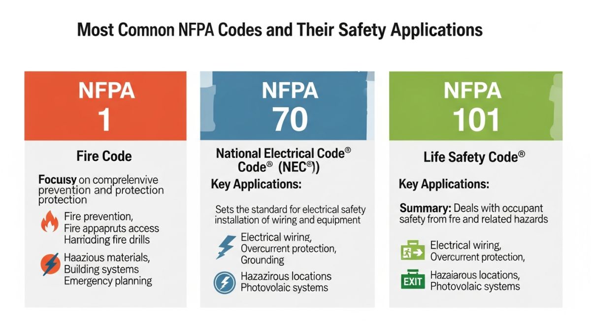
- NFPA 13: Standard for the Installation of Sprinkler Systems. This is the absolute bible for sprinkler system design, detailing spacing, hanger locations, and hydraulic calculation procedures.
- NFPA 15: Standard for Water Spray Fixed Systems for Fire Protection. This standard governs the design of deluge systems used to protect high-hazard equipment like spherical LPG storage tanks, transformers, and process vessels.
- NFPA 20: Standard for the Installation of Stationary Pumps for Fire Protection. This code ensures that the fire pump package can deliver the required flow and pressure without cavitation or mechanical failure.
- NFPA 24: Standard for the Installation of Private Fire Service Mains and Their Appurtenances. This governs the underground piping network that feeds the facility’s hydrants and riser valves.
Hydraulic Calculations: The Hazen-Williams Equation
In my practice, I have seen many young engineers rely blindly on software outputs without understanding the underlying physics. NFPA 13 and NFPA 15 mandate the use of the Hazen-Williams equation to calculate friction losses in fire protection piping. The formula is expressed as:
Where:
- p: Frictional resistance in pounds per square inch (psi) per foot of pipe.
- Q: Flow rate in gallons per minute (gpm).
- C: Friction loss coefficient (dimensionless, representing pipe roughness).
- d: Actual internal diameter of the pipe in inches.
Step-by-Step Engineering Calculation Example
Let us calculate the pressure drop for a 100-foot run of 4-inch Schedule 40 carbon steel pipe (actual internal diameter d = 4.026 inches) carrying a fire water flow rate Q of 500 gallons per minute. For wet pipe systems using carbon steel, NFPA 13 specifies a C-value of 120.
-
Calculate the flow term (Q^1.85):
500^1.85 = 94,803.16 -
Calculate the roughness term (C^1.85):
120^1.85 = 7,118.03 -
Calculate the diameter term (d^4.87):
4.026^4.87 = 878.51 -
Multiply the denominator terms:
7,118.03 * 878.51 = 6,253,260.54 -
Calculate the numerator:
4.52 * 94,803.16 = 428,510.28 -
Divide numerator by denominator to find friction loss per foot (p):
p = 428,510.28 / 6,253,260.54 = 0.0685 psi/ft -
Calculate total loss for 100 feet of pipe:
Total Loss = 0.0685 * 100 = 6.85 psi
If you are designing a system with multiple elbows, tees, and valves, you must add the equivalent length of these fittings to the physical pipe length before calculating the total pressure drop. NFPA 13 provides standard tables for equivalent pipe lengths of fittings to simplify this process.
Never mix up the C-values for wet and dry systems. NFPA 13 mandates a C-value of 120 for wet steel systems, but drops it to 100 for dry systems due to increased corrosion potential. Using 120 for a dry system will lead to an under-designed fire pump and a failed system inspection.
Selecting the correct piping material is a balance between corrosion resistance, mechanical strength, and thermal durability. The table below outlines the standard Hazen-Williams C-values and maximum working pressures for common fire protection piping materials as specified by NFPA 13 and NFPA 24.
| Piping Material | Applicable Standard | Wet System C-Value | Dry System C-Value | Max Working Pressure (psi) |
|---|---|---|---|---|
| Carbon Steel (Sch 10/40) | NFPA 13 / ASTM A53 | 120 | 100 | 300 |
| Ductile Iron (Class 52) | NFPA 24 / AWWA C151 | 140 | N/A (Underground) | 350 |
| Copper Tubing (Type K/L) | NFPA 13 / ASTM B88 | 150 | 150 | 175 |
| CPVC (Chlorinated PVC) | NFPA 13 / ASTM F442 | 150 | N/A (Light Hazard Only) | 175 |
To navigate the complex landscape of fire protection engineering, you must understand how different physical components map to specific regulatory codes. This matrix links key hardware components to their primary design standards and field applications.
| Component / Acronym | Technical Definition | Primary NFPA Reference | Engineering Application |
|---|---|---|---|
| FDC (Fire Dept. Connection) | Inlet pipe connection allowing fire departments to pump water into the system. | NFPA 13 / NFPA 14 | Located on exterior walls, must have clear access and matching thread specs. |
| OS&Y Valve | Outside Screw and Yoke gate valve indicating open/closed status visually. | NFPA 13 / NFPA 24 | Used as isolation valves in fire pump rooms and main service entries. |
| Deluge Valve | Quick-opening valve activated by a fire detection system to flood open nozzles. | NFPA 15 | Installed in high-hazard chemical storage areas and transformer bays. |
| Backflow Preventer | Assembly of check valves preventing fire water from entering potable water mains. | NFPA 24 | Mandatory at the connection point between public water and private mains. |
Field Verification Checklist for Fire Protection Piping
In my experience, the transition from design to construction is where most errors occur. A minor misalignment in a pipe hanger or an uncalibrated pressure gauge can delay authority approval and jeopardize the entire facility’s safety. Use this checklist on-site to verify compliance with NFPA 13 and NFPA 24.
Pre-Commissioning Inspection Points
-
Hydrostatic Testing (NFPA 13 Section 28.2): Verify that the system has been hydrostatically tested at 200 psi (or 50 psi above maximum working pressure if working pressure exceeds 150 psi) for a minimum of 2 hours with zero pressure drop.
-
Pipe Hanger Spacing (NFPA 13 Table 17.4.2.1): Confirm that hanger spacing does not exceed maximum limits (e.g., 12 feet for 1-inch steel pipe, 15 feet for 2-inch and larger steel pipe).
-
Underground Main Flushing (NFPA 24 Section 10.10): Ensure that underground mains are thoroughly flushed prior to connection to the sprinkler system. Verify that the flushing flow rate matches the minimum required velocity of 10 feet per second.
-
Seismic Bracing (NFPA 13 Section 18.5): Inspect lateral and longitudinal sway bracing on all feed and cross mains. Ensure that brace angles match the approved hydraulic calculations.
-
Valve Supervision (NFPA 13 Section 8.16): Confirm that all control valves are locked in the open position or electrically supervised by the fire alarm control panel.
Field Case Study: Real-World Application
During a routine annual performance test at a chemical storage facility, the deluge system protecting a group of methanol storage tanks failed to actuate within the required 40 seconds. Additionally, the primary diesel-driven fire pump experienced severe mechanical vibration and cavitation when operating at 150% of its rated capacity.
Upon investigation, I discovered two major design flaws: the pneumatic pilot line was constructed from carbon steel and had become completely blocked with rust scale, and the pump suction piping had a short-radius elbow installed directly on the suction flange, violating the straight-run requirements of NFPA 20.
I led the remediation team to bring the system back into compliance. First, we replaced the carbon steel pilot lines with corrosion-resistant 316L stainless steel tubing in accordance with NFPA 15. Second, we redesigned the pump suction manifold, replacing the short-radius elbow with a straight pipe run equal to 10 times the pipe diameter (10D) as mandated by NFPA 20 Section 4.21.
During the subsequent flow test, the deluge system actuated in 28 seconds, well below the 40-second limit. The fire pump operated smoothly across its entire performance curve, with zero cavitation and a stable suction pressure profile.
This case study highlights why strict adherence to NFPA codes is non-negotiable. A minor shortcut in piping geometry or material selection can completely disable a multi-million dollar safety system when it is needed most.
Common Questions on NFPA Codes and Standards
What is the difference between an NFPA Code and an NFPA Standard?
Why does NFPA 13 require a lower C-value for dry pipe systems?
What are the straight pipe run requirements for fire pump suction?
Can CPVC piping be used in industrial fire protection systems?
How often must fire protection piping undergo hydrostatic testing?
What is the purpose of a deluge valve in NFPA 15 systems?
===FAQ_BLOCK===
Complete Course on
Piping Engineering
Check Now
Key Features
- 125+ Hours Content
- 500+ Recorded Lectures
- 20+ Years Exp.
- Lifetime Access
Coverage
- Codes & Standards
- Layouts & Design
- Material Eng.
- Stress Analysis

📚 Recommended Resources: NFPA codes and standards
Read these Guides
🎓 Advanced Training


Related posts:
![Super duplex stainless steel piping network on an offshore oil drilling platform.]()
Super Duplex Stainless Steel Oil and Gas Piping Design Guide
![Industrial duplex stainless steel piping system in a chemical processing facility.]()
Understanding Duplex Stainless Steel Properties and Industrial Piping Applications
![A welder performing a critical golden joint weld on an industrial steel pipeline.]()
What is a Golden Joint in Piping Systems?
![A collection of different types of industrial pipes classified by material and size on a storage rack.]()
Comprehensive Guide to Types of Pipes and Industrial Classification Systems
![Industrial piping network with digital overlays representing inch-dia and inch-meter engineering calculations.]()
What are Inch-Dia and Inch-Meter in Piping Systems?
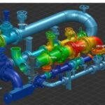
![3D finite element stress analysis model of an industrial piping system showing stress distribution.]()
What Causes Piping System Stresses in Industrial Plants?