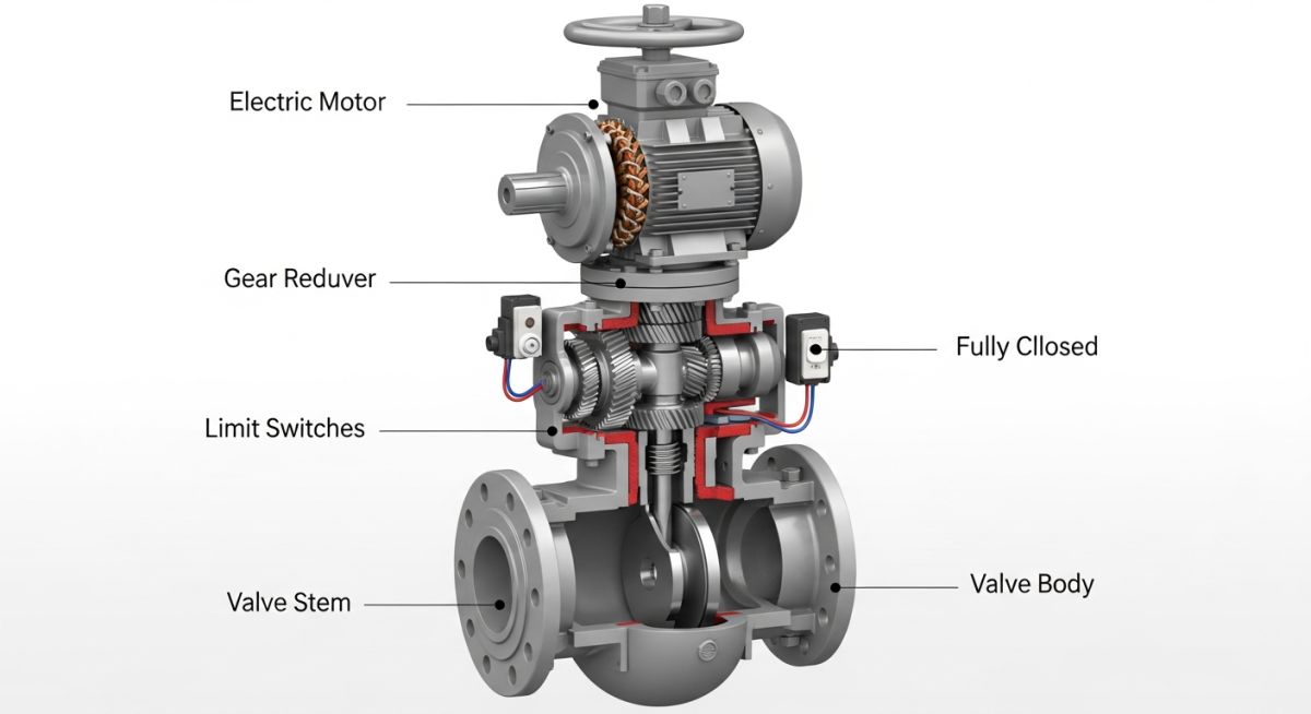
Description: A detailed 3D cross-sectional diagram of a Motor Operated Valve, clearly labeling key components such as the electric motor, gear reducer, limit switches, valve stem, and valve body.
Image Slug: motor-operated-valve-cross-section-diagram
Filename URL: https://epcland.com/wp-content/uploads/2026/06/motor-operated-valve-cross-section-diagram.jpg
What is a Motor Operated Valve? Types, Working, and Specifications
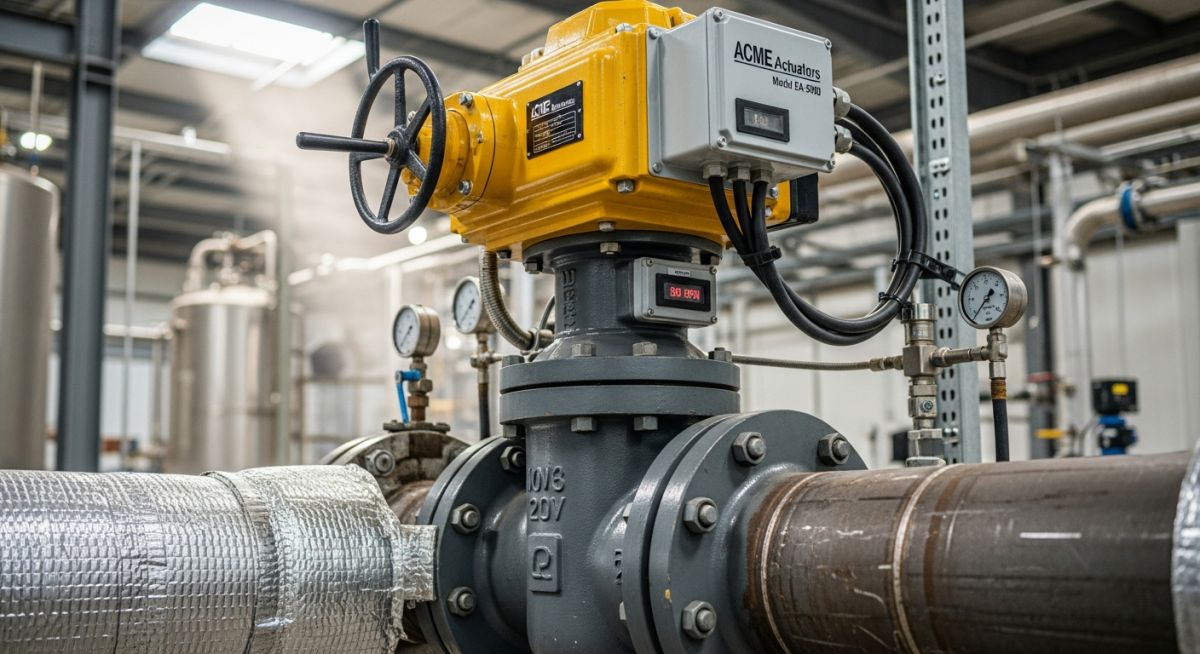
In my 20+ years of commissioning petrochemical plants and heavy industrial piping networks, I have seen many manual valves fail due to sheer human exhaustion or inaccessible locations. That is where the Motor Operated Valve (MOV) becomes the backbone of plant automation. When you are dealing with a 36-inch high-pressure gas line, manual operation is not just impractical; it is a safety hazard. An MOV integrates a mechanical valve body with an intelligent electric actuator, allowing control room operators to isolate lines or modulate flow at the touch of a button.
Understanding the nuances of these systems is critical for any piping designer or plant engineer. From selecting the correct duty cycle to calculating the maximum allowable stem torque, every decision impacts plant safety and operational uptime. In this guide, I will share my field-tested insights on how these valves operate, their primary classifications, and how to specify them accurately on a datasheet.
Key Engineering Takeaways
- Remote automation reduces human error and accelerates emergency shutdown (ESD) response times.
- Proper torque calculation prevents stem deformation and actuator motor burnout.
- Compliance with international standards like API 6D and ASME B16.34 is mandatory for high-pressure applications.
- Regular calibration of limit and torque switches prevents catastrophic mechanical failures.
How Does a Motor Operated Valve Work?
At its core, the working of an MOV relies on the integration of three primary systems: the electrical drive, the gear reduction unit, and the valve mechanical assembly. When the control room sends an open or close signal, the electric motor energizes. Because electric motors run at high speeds with low torque, a gear reduction system (typically utilizing worm gears or planetary gear trains) is used to reduce the speed and multiply the torque.
This multiplied torque is transferred directly to the valve stem. For a gate or globe valve, this torque is converted into linear thrust via a stem nut. For ball or butterfly valves, it translates into a quarter-turn rotational force.
In my early days as a field engineer, I witnessed a gate valve stem buckle like a wet noodle during commissioning. The culprit? An oversized actuator. If the torque switches are set too high or the actuator is oversized, the motor can deliver forces that exceed the Maximum Allowable Stem Torque (MAST) of the valve, leading to catastrophic mechanical failure. Always verify the MAST values on the valve datasheet before coupling any actuator.
Mathematical Modeling of Valve Torque Requirements
To select the correct actuator, we must calculate the total torque required to operate the valve under design differential pressure. The total torque (T_total) is a function of several distinct mechanical resistances:
Where:
- T_packing: The torque required to overcome the friction of the stem packing. This is highly dependent on the packing material (e.g., graphite vs. PTFE) and gland tightness.
- T_seat: The torque required to overcome friction between the valve closing element (disc/ball) and the seat.
- T_hydrostatic: The torque required to overcome the differential pressure force acting on the valve disc.
- SF: Safety Factor (typically 1.3 to 1.5 for standard service, and up to 2.0 for slurry or high-temperature services).
For a rising stem gate valve, the stem thrust (F_stem) must first be calculated:
Where the differential pressure force is:
Here, D_seat is the seat port diameter, Delta_P is the maximum shutoff differential pressure, and f_friction is the friction coefficient of the seat material. Once the thrust is determined, the stem torque is calculated using the stem thread pitch and lead angle parameters.
Selecting the Right Motor Operated Valve
Selecting the correct combination of valve and actuator requires a deep understanding of both the mechanical process and the electrical infrastructure. Below is a comprehensive engineering guide detailing the actuator duty cycles and enclosure ratings required for various industrial environments.
| Actuator Class | Duty Cycle Type | Typical Application | Enclosure Rating (NEMA/IP) | Standard Reference |
|---|---|---|---|---|
| Class A (On-Off) | Short-time duty (S2 – 15 min) | Isolation, Emergency Shutdown (ESD) | NEMA 4/4X, IP67/IP68 | EN 15714-2 |
| Class B (Inching/Positioning) | Intermittent duty (S3 – 25%) | Coarse flow balancing, tank filling | NEMA 4X, IP68 | EN 15714-2 |
| Class C (Modulating) | Continuous duty (S4 – 50% to 100%) | Continuous process control loops | NEMA 7/9 (Explosion Proof), IP68 | IEC 60034-1 |
The table below maps specific valve types to their typical MOV applications, highlighting torque characteristics and key design standards.
| Valve Type | Motion Profile | Torque Profile | Key Design Standard | Critical Field Consideration |
|---|---|---|---|---|
| Gate Valve | Linear (Multi-turn) | High at seating/unseating | API 600 / ASME B16.34 | Susceptible to thermal binding in high-temp steam lines. |
| Globe Valve | Linear (Multi-turn) | High and constant throughout stroke | BS 1873 / ASME B16.34 | High pressure drop; requires high thrust actuators. |
| Ball Valve | Rotary (Quarter-turn) | Peak torque at breakaway and seal entry | API 6D / ISO 17292 | Excellent for fast isolation; seat wear affects breakaway torque. |
| Butterfly Valve | Rotary (Quarter-turn) | Dynamic torque varies with disc angle | API 609 / AWWA C504 | Fluid velocity creates dynamic torque that can oppose actuator. |
Pre-Commissioning Checklist for Your Valve
Before applying electrical power to any newly installed MOV, a rigorous physical inspection is required. Skipping these steps can lead to immediate mechanical damage, motor burnout, or control system faults.
Field Verification Checkpoints
-
Mechanical Alignment: Verify that the valve stem is clean, lubricated with the specified grade of grease, and free of construction debris.
-
Manual Override Check: Engage the manual handwheel and stroke the valve fully open and fully closed. Check for any tight spots or binding.
-
Direction of Rotation: Bump-test the motor briefly to confirm that the valve moves in the correct direction relative to the control signal.
-
Limit Switch Calibration: Set and lock the open and close limit switches. Ensure they trip before the physical travel stops are reached.
-
Torque Switch Settings: Adjust the torque switches to the calculated design values. Do not set them to maximum unless specifically authorized by the design engineer.
-
Enclosure Integrity: Confirm all conduit entries are sealed with explosion-proof compound (if in hazardous areas) and that the enclosure cover O-ring is seated correctly to prevent moisture ingress.
Field Case Study: Real-World Application
During the startup phase of a 150 MW thermal power plant, a 12-inch Class 900 motor-operated gate valve on the main steam bypass line repeatedly failed to open. The valve had been closed tightly while the system was at its operating temperature of 540°C (1004°F). As the system cooled down during a temporary shutdown, the valve body contracted faster than the wedge, locking the wedge tightly between the seats. When the operator attempted to open the valve remotely, the actuator motor tripped on high torque, and manual override with the handwheel proved impossible even with a valve wrench.
To resolve this issue, I led an engineering team to implement a two-fold solution. First, we replaced the solid wedge gate valve with a flexible wedge design in compliance with ASME B16.34, which allows the disc to flex slightly under thermal contraction. Second, we reprogrammed the electric actuator to utilize a “hammer-blow” effect control logic. This logic allows the motor to gain momentum before striking the stem nut, delivering a high-impact force to break the valve free from its seat. Additionally, we adjusted the torque bypass limit switch to ignore torque trips during the first 5% of the opening stroke.
Direct Recommendation: For high-temperature services (above 250°C), avoid using solid wedge gate valves for isolation. Always specify flexible wedges or parallel slide gate valves, and ensure the actuator control logic is configured to handle potential thermal binding scenarios.
Frequently Asked Engineering Questions
What is the difference between an MOV and a Control Valve?
Why do MOVs require a manual handwheel override?
How does a torque switch protect the valve?
What is the significance of the “hammer-blow” effect in actuators?
How do you prevent moisture ingress in MOV actuators?
What standards govern the testing of MOVs?
Complete Course on
Piping Engineering
Check Now
Key Features
- 125+ Hours Content
- 500+ Recorded Lectures
- 20+ Years Exp.
- Lifetime Access
Coverage
- Codes & Standards
- Layouts & Design
- Material Eng.
- Stress Analysis
