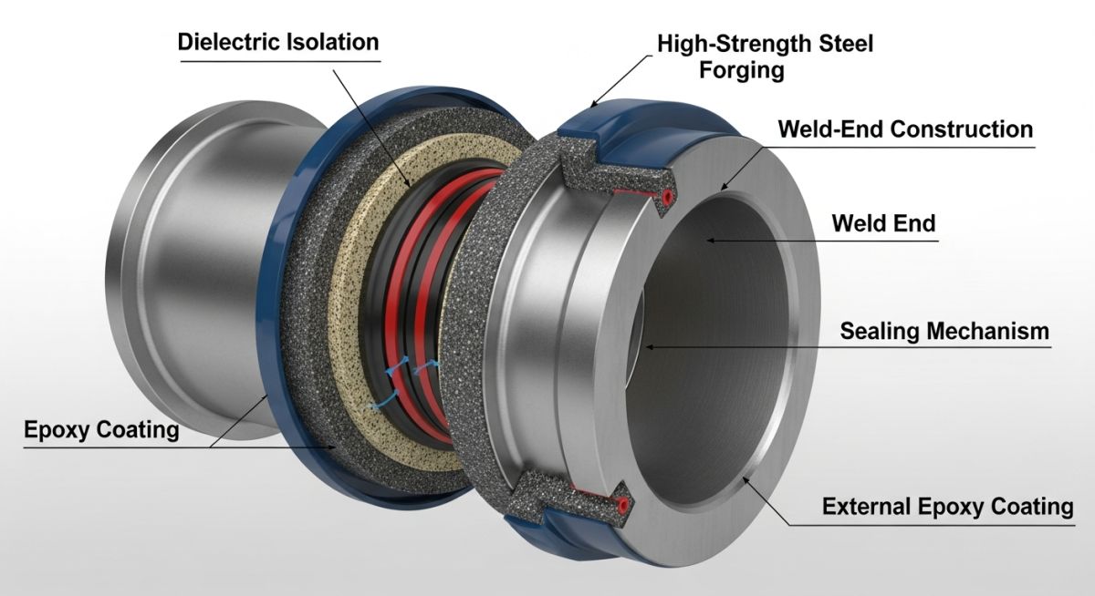
Understanding Monolithic Isolation Joints for Pipeline Integrity
In my two decades of field experience, I have seen far too many cathodic protection systems fail simply because of improper electrical isolation. A Monolithic Isolation Joint (MIJ) is not just a piece of hardware; it is the primary barrier that prevents your pipeline from becoming a sacrificial anode for the entire surrounding infrastructure. Unlike traditional flange insulation kits, which are prone to assembly errors and bolt-torque inconsistencies, the MIJ is a factory-sealed, pressure-tested unit that eliminates the “human factor” during field installation.
When we design for high-pressure transmission lines, we must ensure that the dielectric strength of the joint exceeds the potential difference between protected and unprotected sections. If you are working under ASME B31.3 or ASME B31.4, the MIJ becomes a critical pressure-boundary component that requires rigorous hydrostatic testing and dielectric verification before it ever touches the trench.
Key Takeaways for Pipeline Engineers
- MIJs provide a maintenance-free, factory-tested alternative to traditional flange insulation kits.
- Electrical isolation is mandatory for effective cathodic protection (CP) current containment.
- Design must account for thermal expansion, bending moments, and high-pressure surge conditions.
- Always verify the dielectric strength and hydrostatic test reports against project specifications.
Technical Design of Monolithic Isolation Joints
Monolithic Isolation Joints Design: Engineered pressure-containing assemblies utilizing high-strength dielectric materials to maintain electrical discontinuity while meeting the structural requirements of the connected piping system.
When I evaluate an MIJ for a project, I look at the internal geometry first. The joint consists of two forged steel hubs, an internal sleeve, and a high-dielectric isolation seal. The integrity of the seal is maintained by a series of O-rings and a thermoset resin or epoxy filler that locks the components into a single, monolithic unit. This design ensures that the internal pressure does not cause the dielectric material to extrude or fail under cyclic loading.
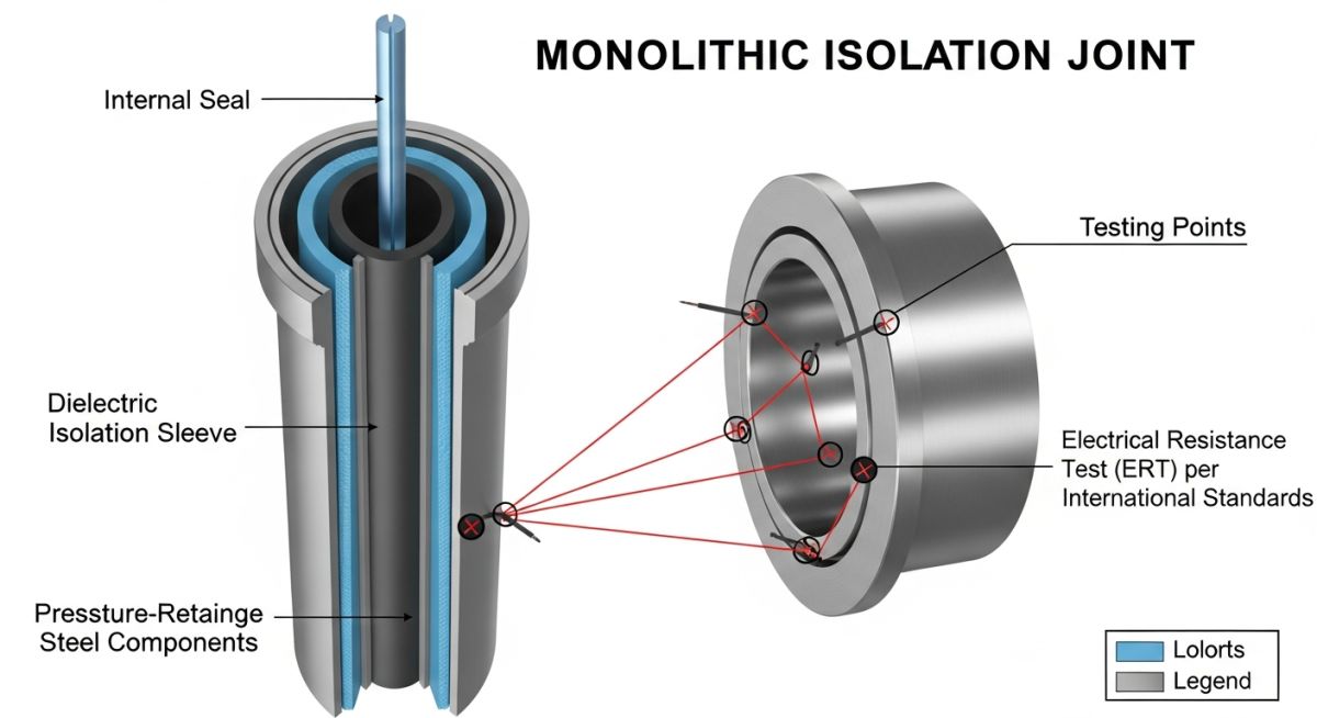
From a stress analysis perspective, the MIJ must be treated as a rigid component in your pipe stress model. Unlike a standard pipe spool, the MIJ has a specific allowable bending moment. If your stress analysis software (like CAESAR II) indicates that the joint will experience moments exceeding the manufacturer’s rating, you must introduce additional supports or anchors to protect the dielectric seal. I have seen joints fail prematurely because the piping system was not properly restrained, leading to excessive shear forces on the internal isolation sleeve.
Critical Design Limitation: Bending Moments
Never assume an MIJ can handle the same bending moment as the adjacent pipe. Always request the “Allowable Bending Moment” data sheet from the manufacturer. If your calculated stress exceeds 60% of the yield strength of the hub material, you are risking a seal breach that will compromise your entire cathodic protection system.
The dielectric strength is typically tested at 5kV or higher. In my experience, the most common point of failure is not the dielectric material itself, but the accumulation of conductive debris or moisture in the annular space if the joint is not properly coated or buried. When specifying these joints, ensure the external coating is compatible with the pipeline’s overall corrosion protection system, such as Fusion Bonded Epoxy (FBE) or liquid epoxy, to prevent external short-circuiting.
For high-pressure gas lines, I always insist on a 1.5 times design pressure hydrostatic test. This is non-negotiable. The test must be performed in the factory, and the documentation must be traceable to the specific serial number of the joint. If the manufacturer cannot provide a certified dielectric test report, do not accept the unit for installation in a critical service environment.
Monolithic Isolation Joints Performance: Evaluation of operational benefits versus structural constraints in high-pressure pipeline applications.
Advantages
- Factory-sealed construction eliminates field assembly errors.
- Superior dielectric strength compared to flange kits.
- Maintenance-free operation for the life of the pipeline.
- Compact design reduces the overall footprint in tight valve stations.
- High resistance to mechanical shock and vibration.
Disadvantages
- Higher initial procurement cost than standard flange kits.
- Cannot be repaired in the field if the seal fails.
- Requires specific handling to avoid damage to the dielectric coating.
- Limited flexibility for field-adjustments during installation.
- Requires precise alignment to prevent excessive bending moments.
Monolithic Isolation Joints Deployment: Strategic implementation of electrical isolation across diverse industrial and energy infrastructure sectors.
Cross-Country Natural Gas Transmission
MIJs are essential at the transition points between transmission lines and compressor stations. By isolating the station piping from the main line, we prevent the cathodic protection current from being drained by the massive grounding grid of the station, ensuring the pipeline remains protected.
Refinery and Terminal Interconnects
In refinery environments, MIJs are used to isolate buried pipelines from above-ground tank farm piping. This prevents galvanic corrosion caused by the contact between different metallic structures and ensures that the CP system is focused solely on the buried assets.
Offshore Platform Riser Protection
For offshore risers, MIJs are installed at the splash zone or near the platform deck to isolate the pipeline from the platform’s structural steel. This prevents the platform’s massive sacrificial anode system from over-protecting the pipeline, which could lead to hydrogen embrittlement in high-strength steels.
When selecting a Monolithic Isolation Joint (MIJ) for high-pressure pipeline service, engineers must evaluate performance metrics against the specific operating environment. The following table outlines the critical design thresholds that dictate the structural integrity and electrical resistance of these components under ASME B31.3 and NACE SP0286 standards.
These parameters are not merely suggestions; they represent the boundary conditions for preventing dielectric breakdown and mechanical failure. In my experience, failing to account for the interaction between thermal expansion and the internal seal material often leads to premature leakage in cryogenic or high-temperature applications. Always verify that the manufacturer’s pressure-temperature rating curve aligns with your project’s specific surge pressure requirements, as the isolation material’s modulus of elasticity changes significantly under extreme thermal cycling.
| Parameter | Standard Range | Critical Consideration |
|---|---|---|
| Dielectric Strength | Greater than 20 kV/mm | Prevents arcing during lightning strikes |
| Insulation Resistance | Min 10 Megaohms at 1kV DC | Ensures effective CP current blocking |
| Hydrostatic Test | 1.5 times Design Pressure | Required per ASME B31.3 protocols |
| Seal Material | Viton or Nitrile (NBR) | Must match fluid chemical compatibility |
The data above serves as a baseline for procurement specifications. Ensure that your vendor provides certified test reports for every unit, as the internal dielectric spacer is the most common point of failure in poorly manufactured joints.
The following matrix maps the essential technical entities involved in the deployment of Monolithic Isolation Joints. Understanding the relationship between these components is vital for maintaining the electrical continuity of the cathodic protection system while ensuring the mechanical robustness of the pipeline segment.
In my professional practice, I have observed that many field failures occur because the isolation joint is treated as a simple pipe spool rather than a complex electromechanical assembly. The matrix below categorizes the primary structural and electrical elements that must be verified during the design review phase to ensure compliance with international standards and site-specific safety requirements.
| Entity | Acronym | Standard Reference |
|---|---|---|
| Monolithic Isolation Joint | MIJ | NACE SP0286 |
| Cathodic Protection | CP | ISO 15589 |
| Process Piping Code | ASME B31.3 | ASME B31.3 |
| Non-Destructive Testing | NDT | ASNT SNT-TC-1A |
By cross-referencing these entities, engineers can establish a comprehensive quality assurance plan. This matrix should be included in the project’s technical documentation to ensure that all stakeholders, from procurement to field installation teams, are aligned on the required performance standards.
Monolithic Isolation Joint Installation Verification: Proper installation is the final barrier against premature corrosion and electrical short-circuiting. Use this checklist to validate that the Monolithic Isolation Joint is prepared for service according to industry best practices.
-
☐
Visual Inspection: Check for any physical damage to the epoxy coating or the external dielectric sleeve. Any scratch deeper than 0.5mm requires immediate repair or rejection. -
☐
Electrical Continuity Test: Perform a pre-installation resistance test using a calibrated megohmmeter. The resistance must exceed 10 Megaohms at 1000V DC. -
☐
Alignment Verification: Ensure the MIJ is installed with zero external stress. Use a laser alignment tool to verify that the pipe ends are perfectly concentric to prevent bending moments on the joint. -
☐
Coating Integrity: Verify that the field joint coating overlaps the factory-applied coating by at least 50mm to prevent moisture ingress at the interface. -
☐
Grounding Check: Confirm that no metallic objects, such as support brackets or temporary scaffolding, are bridging the isolation joint after installation.
In my experience, the most common site error is the “accidental bridge.” This occurs when a welder leaves a stray piece of metal or a grounding clamp across the joint during construction. Always perform a final “short-circuit” check after the pipe is fully backfilled and the cathodic protection system is energized. If the CP system shows a sudden drop in potential, the first step is to inspect the MIJ for any metallic contact that may have been introduced during the final site cleanup.
Problem: Premature Cathodic Protection Failure in a High-Pressure Gas Line
A major pipeline operator reported a total loss of cathodic protection current on a 24-inch transmission line, leading to rapid localized corrosion at the transition zone.
- The Monolithic Isolation Joint was found to be shorted due to internal debris accumulation.
- Excessive bending stress from improper pipe support caused micro-cracks in the dielectric spacer.
- The original installation lacked a surge protection device, allowing lightning-induced arcing to damage the internal insulation.
Outcome: Successful Restoration and System Hardening
The team replaced the damaged unit with a high-integrity MIJ and implemented a comprehensive site-hardening strategy to prevent recurrence.
- Installed a surge arrestor to divert high-voltage transients away from the isolation joint.
- Redesigned the pipe support system to eliminate external mechanical loads on the joint.
- Implemented a quarterly monitoring program using remote telemetry to detect potential shorts in real-time.
My recommendation for similar projects is to always treat the isolation joint as a critical maintenance point. Do not bury the joint in a location that is inaccessible for testing or replacement. If the joint must be buried, install a test station with accessible leads to allow for periodic electrical resistance measurements without requiring excavation.
What is the primary function of a Monolithic Isolation Joint?
- Prevents galvanic corrosion by isolating dissimilar metals.
- Allows for the segmentation of the pipeline into manageable cathodic protection zones.
- Ensures that the pipeline remains electrically isolated from grounded station equipment.
How do I verify the electrical integrity of an MIJ?
- Disconnect all external grounding or surge protection devices before testing.
- Measure the resistance between the two sides of the joint; it should be in the megaohm range.
- Compare the results against the manufacturer’s baseline data provided in the factory test report.
Can an MIJ be used in high-pressure gas service?
- The internal seal design is pressure-energized to ensure a leak-tight connection.
- The steel components are forged and welded to meet ASME B31.3 or B31.8 requirements.
- Each unit undergoes rigorous hydrostatic and pneumatic testing before leaving the factory.
What causes an MIJ to fail prematurely?
- Improper pipe support leading to excessive bending moments.
- Lightning strikes or high-voltage power line interference causing dielectric breakdown.
- Chemical incompatibility between the seal material and the pipeline fluid.
How does an MIJ differ from a flange isolation kit?
- MIJs are more robust and less prone to installation errors compared to flange kits.
- Flange kits require precise bolt torque management, whereas MIJs are ready for immediate welding.
- MIJs offer superior resistance to environmental degradation and mechanical stress.
Are there specific standards for MIJ testing?
- NACE SP0286 provides the standard for electrical isolation and cathodic protection.
- ASME B31.3 and B31.8 define the pressure-containing requirements for the steel components.
- ISO 15589 outlines the requirements for cathodic protection systems, including the use of isolation joints.
📚 Recommended Resources: Monolithic Isolation Joints
Complete Course on
Piping Engineering
Check Now
Key Features
- 125+ Hours Content
- 500+ Recorded Lectures
- 20+ Years Exp.
- Lifetime Access
Coverage
- Codes & Standards
- Layouts & Design
- Material Eng.
- Stress Analysis
