Top 10 Mechanical Engineering Software Tools to Master in 2026
Over my 20 years in the piping and mechanical design industry, I have watched our tools evolve from basic 2D drafting boards to highly integrated, cloud-enabled simulation ecosystems. In my experience, selecting the right software suite is not just about buying a license; it is about matching your specific engineering workflows, code compliance needs, and manufacturing constraints to the right computational engine.
Whether you are designing high-pressure piping manifolds under ASME B31.3 or optimizing aerodynamic profiles for rotating machinery, the software you choose dictates your margin of safety and your speed to market. Let us cut through the marketing noise and look at the actual tools driving the industry today.
- CAD and FEA integration reduces design cycle times by up to forty percent.
- Compliance with ASME Section VIII and ISO 9001 requires rigorous software verification.
- Cloud-based collaboration tools are transforming multi-disciplinary engineering workflows.
Complete Course on
Piping Engineering
Check Now
Key Features
- 125+ Hours Content
- 500+ Recorded Lectures
- 20+ Years Exp.
- Lifetime Access
Coverage
- Codes & Standards
- Layouts & Design
- Material Eng.
- Stress Analysis
Evaluating Modern Mechanical Engineering Software Options
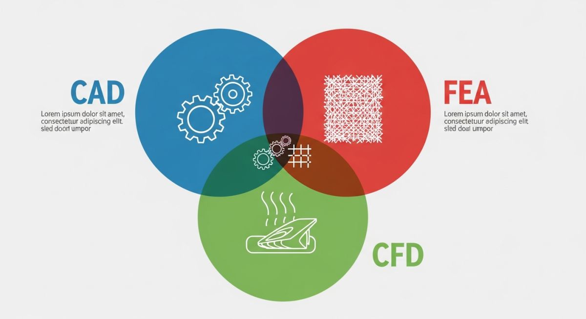
Software Selection Criteria: The systematic evaluation of CAD, FEA, and CFD platforms based on computational accuracy, API integration, and compliance with ASME Section VIII design rules.
When evaluating mechanical design tools, I look at three core pillars: geometric modeling fidelity, solver accuracy, and interoperability. In my experience, a tool that cannot seamlessly export clean STEP files or handle native parasolids will cost you hundreds of hours in geometry cleanup.
Let us break down the top 10 tools that dominate the industrial landscape in 2024:
- SolidWorks: The industry standard for mid-range 3D parametric modeling. Excellent for weldments, sheet metal, and rapid prototyping.
- Autodesk Inventor: A powerful competitor to SolidWorks, featuring superb dynamic simulation and native integration with AutoCAD DWG workflows.
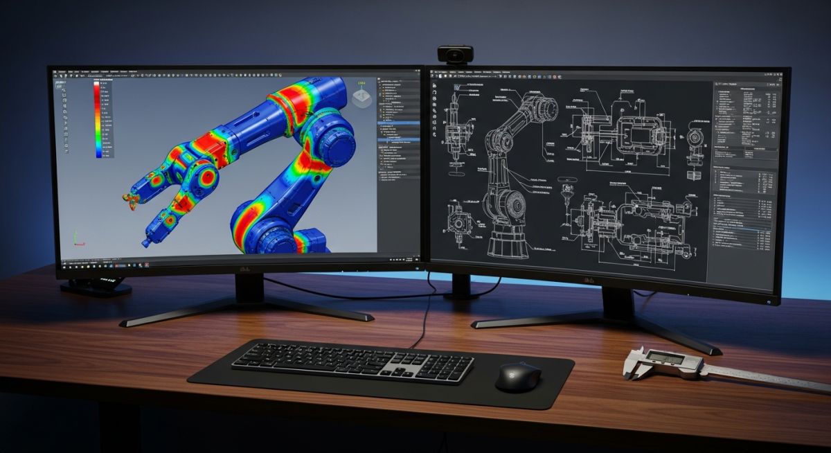
- ANSYS Mechanical: The gold standard for finite element analysis (FEA). I rely on this for complex non-linear contact, fatigue analysis, and seismic validation.
- CATIA: The powerhouse of aerospace and automotive design. Unmatched surface modeling capabilities and large assembly management.
- PTC Creo: Highly robust parametric CAD tool, favored for complex product configurations and top-down assembly design.
- Fusion 360: A cloud-enabled platform combining CAD, CAM, and CAE. Ideal for startups and agile engineering teams.
- MATLAB/Simulink: The ultimate platform for system-level dynamic modeling, control systems, and mathematical analysis.
- ANSYS Fluent: The premier computational fluid dynamics (CFD) solver for complex thermal-fluid interactions and multiphase flows.
- AutoCAD: Still the undisputed king for 2D piping and instrumentation diagrams (P&IDs) and structural layouts.
- COMSOL Multiphysics: Excellent for coupled physics simulations, such as electromagnetic heating or acoustic-structural interactions.
Never trust default software outputs blindly. In my 20 years of engineering, I have seen catastrophic structural failures caused by designers accepting default mesh sizes and unverified boundary conditions in FEA packages. Always perform a manual grid convergence study.
Analytical Stress Calculations vs Software Solvers
Stress Verification Formula: The mathematical validation of software-generated stress values using classical mechanics equations to ensure solver convergence and accuracy.
To verify FEA results for a pressurized cylinder, we use the classical Lame equations for thick-walled vessels. The hoop stress (S_h) is calculated as:
Where:
P = Internal design pressure (MPa)
R_o = Outer radius of the cylinder (mm)
R_i = Inner radius of the cylinder (mm)
If your FEA software outputs a Von Mises stress that deviates by more than five percent from this analytical calculation in a simple geometry model, your mesh density is likely inadequate or your boundary conditions are over-constraining the model.
Comparing Leading Mechanical Engineering Software Tools
Engineering Software Comparison: A structured technical matrix evaluating CAD, FEA, and CFD platforms based on licensing, primary application, and industry-standard compliance.
| Software Name | Primary Domain | Key Strength | Applicable Standards |
|---|---|---|---|
| SolidWorks | Parametric 3D CAD | User interface, rapid modeling | ISO 128, ASME Y14.5 |
| ANSYS Mechanical | Finite Element Analysis | Non-linear stress, fatigue | ASME Section VIII Div 2 |
| CATIA | High-End CAD/CAM | Complex surfacing, aerospace | ISO 10303 (STEP) |
| ANSYS Fluent | Fluid Dynamics (CFD) | Turbulence, thermal transfer | API 520/521 validation |
| PTC Creo | Parametric CAD | Large assembly performance | ASME Y14.100 |
This technical mapping links software capabilities directly to physical engineering parameters and regulatory compliance frameworks.
| Entity / Acronym | Physical Parameter | Software Solver Type | Standard Reference |
|---|---|---|---|
| FEA (Finite Element) | Von Mises Stress, Strain | Implicit / Explicit Solver | ASME Sec VIII Div 2 |
| CFD (Fluid Dynamics) | Pressure Drop, Velocity | Navier-Stokes Solver | API RP 520 |
| GD&T (Dimensioning) | Geometric Tolerances | Parametric CAD Engine | ASME Y14.5-2018 |
Software Deployment and Verification Checklist
Software Verification Protocol: A rigorous quality assurance checklist designed to validate engineering software installations against ASME NQA-1 and ISO 9001 standards before production release.
Before deploying any new mechanical design or simulation tool across your engineering team, it is critical to run a formal verification protocol. In my experience, skipping this step leads to version mismatches and corrupted design files.
-
Hardware Compatibility Check
Verify that workstation GPUs are certified by the software vendor to prevent display driver crashes during large assembly rendering. -
Benchmark Problem Validation
Run standard benchmark problems (e.g., NAFEMS benchmarks for FEA) to verify solver accuracy against known analytical solutions. -
Template and Library Standardization
Lock down shared material databases, drawing templates, and standard fastener libraries on a secure network drive. -
PDM/PLM Integration Test
Confirm that the CAD tool check-in and check-out workflows function correctly with your Product Data Management system.
Field Case Study: Real-World Application
A high-pressure gas manifold designed using legacy CAD software suffered a catastrophic fatigue crack at a branch connection during commissioning. The original design team had relied on simplified 2D beam elements for stress analysis, completely missing the localized stress concentration factors at the crotch corner of the tee.
I stepped in and remodeled the entire manifold using SolidWorks, then imported the geometry into ANSYS Mechanical for a full 3D solid-element FEA. By applying the stress linearization guidelines of ASME Section VIII Division 2, we identified that the local membrane plus bending stress exceeded the allowable limit by forty-five percent. We redesigned the reinforcement pad and optimized the support locations, reducing the peak stress to safe levels.
My direct recommendation: Never rely on simplified 1D or 2D modeling for high-pressure, cyclic-service systems. Always utilize modern 3D parametric CAD integrated with high-fidelity FEA solvers to capture localized stress concentrations.
Frequently Asked Engineering Questions
Which software is best for ASME Section VIII pressure vessel design?
Can Fusion 360 replace SolidWorks for industrial design?
How do I verify the accuracy of my CFD simulation?
Is MATLAB considered mechanical engineering software?
What is the role of PLM software in engineering?
How does GD&T integrate with modern CAD software?