What is Level Measurement? Its Types, Working, and Advantages
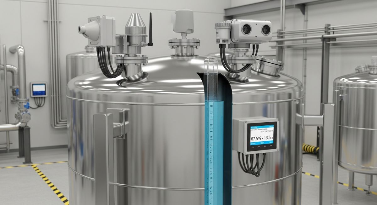
In my 20 years of managing piping systems and tank farms, I have seen how a single failed level sensor can disrupt an entire refinery. Level measurement is not just about knowing how full a tank is; it is about process safety, preventing catastrophic overfills, and maintaining mass balance. Whether you are dealing with cryogenic liquids, corrosive acids, or granular solids, selecting the correct instrument is a fundamental engineering decision.
- Understand the fundamental difference between direct and indirect level measurement.
- Learn how to select between contact and non-contact sensors based on fluid properties.
- Discover the mathematical principles governing hydrostatic and radar level instruments.
- Review real-world field challenges and commissioning checklists to ensure zero-fault startups.
Why Level Measurement Matters in Process Industries
Process Level Control: The continuous monitoring of fluid boundaries to prevent hazardous dry-run or overfill conditions in pressurized vessels. This practice adheres strictly to safety integrity level guidelines outlined in IEC 61511.
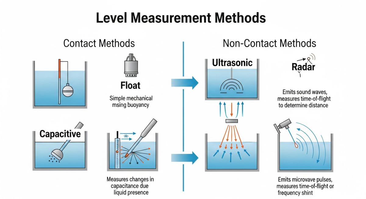
In my experience, level instruments are divided into two primary categories: direct (or intrusive) and indirect (or inferential). Direct methods measure the actual physical height of the medium, whereas indirect methods infer the level by measuring another physical property, such as hydrostatic pressure, dielectric constant, or acoustic travel time.
The Physics of Hydrostatic Level Measurement
Hydrostatic level measurement relies on the principle that the pressure exerted by a liquid column at rest is directly proportional to its height. The governing equation is:
Where:
- P = Hydrostatic pressure (Pascals, Pa)
- rho (ρ) = Fluid density (kg/m³)
- g = Acceleration due to gravity (9.81 m/s²)
- h = Height of the liquid column (meters, m)
When dealing with pressurized vessels, we must use differential pressure (DP) transmitters. The high-pressure side connects to the bottom of the vessel, while the low-pressure side connects to the vapor space. This cancels out the blanket gas pressure, leaving only the true hydrostatic head of the liquid.
Selecting Level Measurement Technologies for Harsh Environments
Technology Selection: The engineering process of matching fluid characteristics, vessel geometry, and environmental conditions to the optimal sensor design. This selection process ensures long-term reliability and minimizes maintenance costs under API RP 551 guidelines.
When selecting a level transmitter, I always evaluate the dielectric constant of the medium. For low-dielectric fluids like hydrocarbons, Guided Wave Radar (GWR) is highly effective because the probe guides the high-frequency electromagnetic pulses directly to the surface, minimizing signal attenuation. For non-contact applications, non-contacting radar operating at high frequencies (e.g., 80 GHz) provides a narrow beam angle, avoiding internal vessel obstructions like agitators and heating coils.
| Technology | Type | Optimal Fluids | Max Temp / Pressure | Key Limitations |
|---|---|---|---|---|
| Differential Pressure | Contact (Indirect) | Clean liquids, water, oils | Up to 400°C / 400 bar | Density changes cause calibration drift |
| Guided Wave Radar (GWR) | Contact (Direct) | Hydrocarbons, acids, solids | Up to 450°C / 400 bar | Probe coating, mechanical stress on probe |
| Non-Contact Radar | Non-Contact (Direct) | Corrosive chemicals, slurries | Up to 200°C / 160 bar | Low dielectric fluids reduce signal strength |
| Ultrasonic | Non-Contact (Direct) | Water, wastewater, open channels | Up to 150°C / 4 bar | Affected by foam, dust, and vapor blankets |
| Entity / Parameter | Acronym | Physical Property Measured | Applicable Standard |
|---|---|---|---|
| Differential Pressure Transmitter | DPT | Hydrostatic Head Pressure | ASME B40.100 |
| Guided Wave Radar | GWR | Electromagnetic Time of Flight | IEC 60079-11 |
| Safety Integrity Level | SIL | Probability of Failure on Demand | IEC 61508 |
Commissioning Checklist for Level Measurement Systems
Commissioning Verification: The systematic field execution of physical, electrical, and calibration checks to guarantee the safe operation of level sensors. This protocol aligns with the quality assurance guidelines of ISA-RP60.3.
During plant commissioning, I follow a strict verification sequence to prevent dry-run damage to pumps and vessel overfills. Use this checklist before introducing process fluids into the system:
Pre-Commissioning Field Steps
-
Mechanical Alignment: Verify that the nozzle orientation is vertical within +/- 1 degree to prevent radar signal deflection or probe contact with vessel walls.
-
Stilling Well Inspection: Ensure stilling wells are free of weld slag, burrs, or internal obstructions that could interfere with float movement or radar signals.
-
Zero and Span Calibration: Perform a wet calibration or dry configuration check matching the actual fluid density at operating temperature.
-
Loop Integrity Check: Confirm that the 4-24mA HART signal or digital fieldbus output matches the DCS reading at 0%, 25%, 50%, 75%, and 100% span.
-
Isolation Valve Verification: Ensure all root valves and manifold valves are fully open, and bleed valves are tightly closed and plugged.
Field Case Study: Real-World Application
At a major petrochemical facility, a high-pressure separator vessel experienced frequent level control failures. The existing differential pressure transmitter suffered from calibration drift due to rapid temperature swings and heavy foaming at the liquid-gas interface. This caused false high-level alarms, triggering emergency shutdowns that cost the plant over 120,000 per hour in lost production.
I recommended replacing the DP transmitter with a coaxial Guided Wave Radar (GWR) transmitter. The coaxial probe isolated the radar signal from the turbulent foam layer and eliminated the density-dependence issues. Following installation, the level reading remained stable within +/- 2mm, completely eliminating false trips and saving the facility an estimated 1.4 million in annual downtime.
My Recommendation: When dealing with fluids prone to foaming, flashing, or rapid density changes, avoid hydrostatic pressure methods. Instead, opt for Guided Wave Radar or high-frequency non-contact radar to ensure a stable, direct measurement of the liquid surface.
Frequently Asked Engineering Questions
What is the difference between contact and non-contact level measurement?
How does temperature affect hydrostatic level transmitters?
When should I use Guided Wave Radar (GWR) over Non-Contact Radar?
What is the impact of foam on ultrasonic level sensors?
How does a displacer level transmitter work?
Which standards govern industrial level measurement installations?
===
Complete Course on
Piping Engineering
Check Now
Key Features
- 125+ Hours Content
- 500+ Recorded Lectures
- 20+ Years Exp.
- Lifetime Access
Coverage
- Codes & Standards
- Layouts & Design
- Material Eng.
- Stress Analysis

📚 Recommended Resources: level measurement
Read these Guides
- 📄 What is Flash Point? Its Significance, Measurement, and Examples
- 📄 Pour Point of Crude Oil: Definition, Significance, Features, Measurements & Factors
- 📄 Vibration Measurement: Instruments, Units, and Applications Explained
- 📄 What is Instrumentation Engineering? Systems, Components & Examples (2026 Guide)


Related posts:
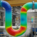
![3D engineering visualization of a piping system undergoing thermal expansion with stress concentration points highlighted in red and yellow.]()
Piping Flexibility Analysis: Essential Requirements for Safe Industrial Design
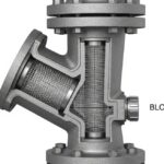
![Industrial Y-type piping strainer installed in a high-pressure steel pipeline with visible flanged connections and blow-off valve.]()
Piping Strainers: Design Standards, Selection Criteria, and Industrial Applications
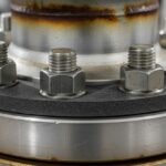
![Industrial flange connection with high-strength alloy steel studs and nuts in a refinery piping system.]()
How to Select a Bolt: The Complete Engineering Selection Process
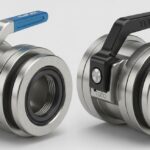
![Close-up view of industrial Elaflex and Todo hose couplings showing locking mechanisms and stainless steel construction for chemical transfer.]()
Industrial Hose Couplings: Elaflex and Todo Coupling Design Guide
![3D isometric plot plan showing the strategic placement of reactors, fired heaters, and pressure vessels in a refinery.]()
Strategic Location of Static Equipment: Fired Heaters, Reactors, and Drums
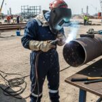
![Professional welder performing high-precision field welding on industrial piping in a refinery construction site.]()
General Requirements for Field Welding: A Piping Engineering Guide