What is Flash Point? Its Significance, Measurement, and Examples
In my 20+ years of designing piping systems and managing process safety for oil refineries and chemical plants, I have seen how a single misunderstood physical property can lead to catastrophic failure. That property is the flash point. When we design piping networks, select pump seals, or establish hazardous area classifications, the flash point of the process fluid is the line of demarcation between a safe operating environment and a potential bomb.
Understanding this parameter is not just about passing a laboratory test; it is about knowing how a fluid behaves under pressure, temperature fluctuations, and upset conditions. If you operate a system above a fluid’s flash point, any small leak can instantly find an ignition source and trigger a devastating flash fire.
- The flash point is the absolute baseline for determining safe storage and handling temperatures of volatile liquids.
- Closed-cup testing methods provide a more conservative and accurate safety margin for process piping design than open-cup methods.
- Operating a system above a fluid’s flash point requires strict adherence to explosion-proof electrical standards and nitrogen blanketing.
Complete Course on
Piping Engineering
Check Now
Key Features
- 125+ Hours Content
- 500+ Recorded Lectures
- 20+ Years Exp.
- Lifetime Access
Coverage
- Codes & Standards
- Layouts & Design
- Material Eng.
- Stress Analysis
Why Flash Point Dictates Process Safety Standards
Flash Point Safety Thresholds: The critical temperature boundaries that define whether a fluid poses an immediate fire hazard during storage, pumping, and processing operations. These thresholds dictate the selection of explosion-proof electrical equipment and hazardous area classifications under NFPA 70.
To understand the physics of a flash point, we must look at the relationship between vapor pressure and temperature. Every liquid exerts a vapor pressure that increases as temperature rises. When a liquid reaches its flash point, the concentration of vapor in the air immediately above the liquid surface reaches the Lower Flammable Limit (LFL) or Lower Explosive Limit (LEL).
We can model this behavior using Raoult’s Law and the Antoine Equation to estimate the vapor phase concentration. The partial pressure of the volatile component (P_i) in the vapor space is calculated as:
Where x_i is the mole fraction of the component in the liquid phase, and P_sat(T) is the saturated vapor pressure at temperature T. The flash point is reached when the mole fraction of the vapor in the air (y_i) equals the LFL:
This mathematical relationship explains why even a minor contamination of a high-flash-point fluid with a highly volatile solvent can drastically lower the overall mixture’s flash point—a phenomenon known as flash point depression.
Open Cup vs. Closed Cup Testing Methods
In the laboratory, we measure this property using two primary methodologies: Closed Cup and Open Cup.
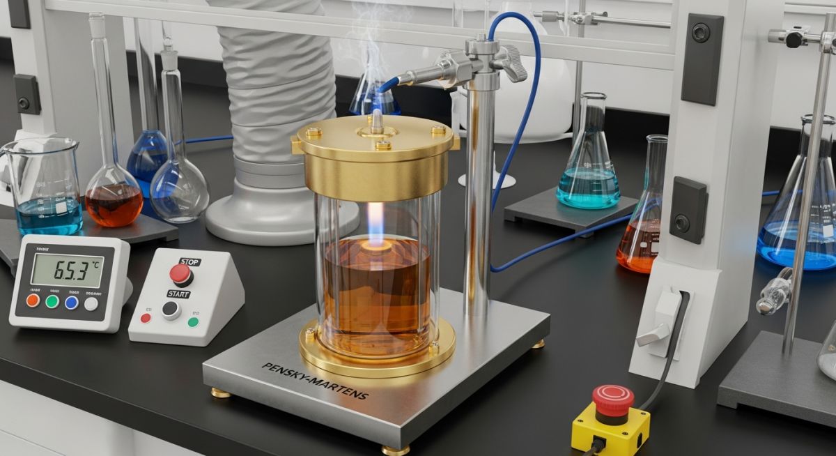
- Closed Cup (e.g., ASTM D93 Pensky-Martens): The liquid is heated in a closed brass cup, and an ignition source is introduced through a shutter. Because the vapors are confined, this method prevents the escape of highly volatile light ends. It yields a lower, more conservative flash point, making it the industry standard for process safety and piping design.
- Open Cup (e.g., ASTM D92 Cleveland Open Cup): The liquid is heated in an open vessel, allowing vapors to diffuse into the atmosphere. This method simulates open-air spills or open-top tank scenarios. It typically yields a higher flash point because the vapors are allowed to escape.
Never assume a fluid’s flash point remains static. In high-temperature heat transfer systems, thermal cracking breaks down long-chain hydrocarbons into highly volatile, low-boiling-point fractions. This process can lower a fluid’s flash point by over 100°C, turning a stable Class IIIB combustible liquid into a highly volatile Class IA flammable hazard without any visible change in the system.
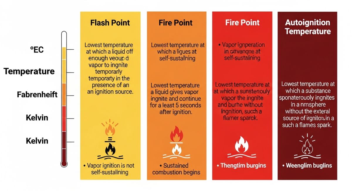
As shown in the infographic above, the flash point is only the first stage of ignition. While the flash point requires an external ignition source and only produces a brief flash, the fire point is the temperature at which the vapor continues to burn for at least 5 seconds after ignition. The fire point is typically 5°C to 30°C higher than the flash point.
Flash Point Examples for Common Industrial Fluids
Industrial Fluid Flash Points: Standardized temperature values representing the ignition thresholds of common hydrocarbons, solvents, and lubricants under atmospheric pressure. These values are critical for designing safe storage tanks, piping systems, and ventilation networks in accordance with API Standards.
| Fluid Name | Flash Point (°C / °F) | Test Method | NFPA 30 Class | Autoignition Temp (°C) |
|---|---|---|---|---|
| Acetone | -20°C / -4°F | ASTM D56 (TCC) | Class IB (Flammable) | 465°C |
| Gasoline (100 Octane) | -43°C / -45°F | ASTM D56 (TCC) | Class IA (Flammable) | 280°C |
| Ethanol (96%) | 13°C / 55°F | ASTM D93 (PMCC) | Class IB (Flammable) | 363°C |
| Kerosene | 38°C to 72°C / 100°F to 162°F | ASTM D93 (PMCC) | Class II (Combustible) | 220°C |
| Diesel Fuel (No. 2-D) | >52°C / >125°F | ASTM D93 (PMCC) | Class II (Combustible) | 256°C |
| Lube Oil (ISO VG 46) | 220°C / 428°F | ASTM D92 (COC) | Class IIIB (Combustible) | 350°C |
| Entity / Acronym | Technical Definition | Physical Parameter Impact | Reference Standard |
|---|---|---|---|
| LEL / LFL | Lower Explosive/Flammable Limit in air. | Determines the minimum vapor concentration required for ignition at the flash point. | NFPA 325 |
| PMCC | Pensky-Martens Closed Cup tester. | Standardized closed-cup method for fuel oils, lube oils, and viscous liquids. | ASTM D93 |
| COC | Cleveland Open Cup tester. | Standardized open-cup method for viscous petroleum products and lubricants. | ASTM D92 |
| NFPA 30 | Flammable and Combustible Liquids Code. | Classifies liquids based on flash point and boiling point to dictate storage requirements. | NFPA 30 |
Verifying Flash Point Safety on Site
Flash Point Field Verification: The systematic process of auditing operating temperatures, vapor containment systems, and electrical classifications against the actual flash points of processed fluids. This protocol ensures compliance with OSHA 1910.106 and prevents catastrophic ignition events.
When conducting pre-commissioning safety audits or routine hazard reviews, I use a rigorous verification protocol. This checklist ensures that the physical properties of the fluid align perfectly with the mechanical and electrical design of the piping system.
Piping & Process Safety Verification Checklist
-
Operating Temperature Margin: Verify that the maximum operating temperature of the fluid is maintained at least 10°C (18°F) below its closed-cup flash point, unless the system is specifically designed for flammable vapor containment.
-
Hazardous Area Classification: Confirm that all electrical equipment, junction boxes, and instrumentation within the process area match the Class/Division requirements specified by NFPA 70 for the fluid’s flash point class.
-
Nitrogen Blanketing: Ensure that storage tanks and expansion vessels containing fluids operated near or above their flash point are equipped with an active nitrogen blanketing system to displace oxygen.
-
Thermal Degradation Monitoring: Establish a semi-annual laboratory testing schedule for heat transfer fluids and lubricating oils to detect flash point depression caused by thermal cracking.
-
Flange Guard Installation: Install physical spray shields (flange guards) on all piping flanges carrying fluids above their flash point to prevent pressurized aerosolization in the event of a gasket failure.
Field Case Study: Real-World Application
During a routine safety audit at a chemical processing facility, I discovered that a synthetic heat transfer fluid (HTF) system was operating at 160°C. The original fluid specification sheet listed a closed-cup flash point of 195°C, which initially seemed safe. However, laboratory analysis of a physical sample revealed that the fluid’s flash point had dropped to 58°C due to severe thermal cracking. The system was operating more than 100°C above its actual flash point, and the expansion tank lacked a nitrogen blanket, creating an immediate explosion hazard.
We immediately isolated the system and executed a controlled shutdown. The degraded fluid was drained and replaced with fresh HTF. To prevent a recurrence, we designed and installed an automated nitrogen blanketing system on the expansion tank to maintain an oxygen concentration below 2%. We also updated the plant’s standard operating procedures to mandate ASTM D93 closed-cup testing of the HTF every six months, establishing a proactive fluid replacement threshold before the flash point could drop below 120°C.
This case highlights why relying solely on manufacturer data sheets for aged fluids is a dangerous practice. Regular physical testing is the only way to guarantee process safety in high-temperature operations.
Frequently Asked Engineering Questions
What is the difference between flash point and fire point?
Why is closed cup testing preferred over open cup testing?
How does pressure affect the flash point of a liquid?
What is the relationship between flash point and autoignition temperature?
How does thermal degradation lower the flash point of heat transfer fluids?
What are the NFPA classifications for flammable and combustible liquids?
===
