Table of Contents

What are Inch-Dia and Inch-Meter in Piping Systems?
In my 20 plus years of managing large-scale petrochemical and refinery piping projects, I have seen many young engineers struggle with project estimates. They often ask me how a project manager can accurately predict the man-hours needed to weld and erect thousands of meters of piping of varying diameters. The answer does not lie in tracking simple linear meters or counting individual welds. Instead, we rely on two fundamental metrics: Inch-Dia and Inch-Meter.
When I was working on a major refinery expansion early in my career, we had over fifty thousand piping joints to weld. Trying to estimate the labor force using only the total number of joints led to massive scheduling errors because welding a 24-inch heavy-wall pipe takes significantly longer than welding a 2-inch utility line. By converting our entire bill of materials into standardized work units, we established a reliable baseline that kept our construction schedule on track.
Key Takeaways for Piping Engineers
- Understand how Inch-Dia standardizes welding and fabrication labor across different pipe sizes.
- Learn how Inch-Meter acts as the primary metric for piping erection, rigging, and insulation.
- Master the exact mathematical formulas to convert raw piping bills of materials into actionable project management data.
- Discover how to apply these metrics to prevent contractor billing disputes and schedule overruns.
Understanding Inch-Dia and Inch-Meter in Piping
To manage any piping project effectively, we must separate the fabrication work from the erection work. Fabrication primarily happens in the shop and revolves around cutting, beveling, fit-up, and welding. Erection happens in the field and involves rigging, positioning, bolting, and supporting the piping spools. This is where our two key metrics come into play.
1. Inch-Diameter (Inch-Dia) Explained
Inch-Dia is the universal currency of the piping welder. It represents the volume of welding work required for a project. In my experience, using raw joint counts is highly misleading. A single weld joint on a 12-inch pipe requires much more weld metal, heating, and time than a joint on a 3-inch pipe.
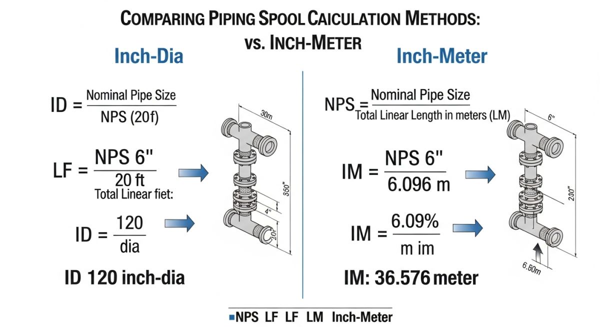
The formula to calculate Inch-Dia is straightforward:
For example, if you have ten joints of 6-inch pipe, the calculation is:
6 inches x 10 joints = 60 Inch-Dia.
If you have five joints of 12-inch pipe, the calculation is:
12 inches x 5 joints = 60 Inch-Dia.
Even though the pipe sizes and joint quantities differ, the total welding work units are identical. This allows project planners to allocate man-hours consistently. Typically, a standard welder productivity rate might be expressed as 8 to 12 Inch-Dia per shift, depending on the material grade, wall thickness, and welding process specified by ASME B31.3 Process Piping.
2. Inch-Meter (Inch-Mtr) Explained
While Inch-Dia handles the welding, Inch-Meter tracks the physical handling, transport, alignment, and installation of the piping spools on site. It also serves as the baseline for estimating sandblasting, painting, and thermal insulation.
The formula to calculate Inch-Meter is:
For example, if you need to erect 50 meters of 8-inch piping, the calculation is:
8 inches x 50 meters = 400 Inch-Meters.
This metric accounts for both the weight and the physical size of the pipe. A larger diameter pipe weighs more per meter and requires heavier rigging equipment, more crane time, and larger crews. By using Inch-Meters, we can apply a standardized erection factor (such as 1.5 man-hours per Inch-Meter) to determine the total field labor force required.
Below is a practical engineering data table that I use during the initial FEED (Front-End Engineering Design) phase to convert a standard piping bill of materials into work units. This table demonstrates how different pipe schedules and sizes yield distinct Inch-Dia and Inch-Meter values.
| Line ID | NPS (Inches) | Schedule | Length (Meters) | No. of Joints | Total Inch-Dia | Total Inch-Meter |
|---|---|---|---|---|---|---|
| 10-HC-001 | 4 | Sch 40 | 120 | 24 | 96 | 480 |
| 12-PD-005 | 8 | Sch 80 | 85 | 18 | 144 | 680 |
| 16-SG-012 | 12 | Sch STD | 45 | 10 | 120 | 540 |
| 08-LO-022 | 2 | Sch XS | 210 | 42 | 84 | 420 |
To ensure your project database aligns with standard industry practices, use this technical mapping matrix. It links physical parameters to their corresponding project management applications and standard references.
| Metric Name | Acronym | Primary Application | Key Variables | Standard Reference |
|---|---|---|---|---|
| Inch-Diameter | ID / WID | Welding, Shop Fabrication, NDT Planning | NPS, Joint Count, Joint Type | ASME B31.3 |
| Inch-Meter | IM / EIM | Field Erection, Rigging, Painting, Insulation | NPS, Linear Length, Support Spacing | API Standards |
| Diameter-Inch-Factor | DIF | Welder Productivity Adjustments | Wall Thickness, Material Grade | AWS D10.10 |
Calculating Inch-Dia and Inch-Meter in Piping
Before you approve any progress payments or update your project schedule, you must verify the physical work completed on site. Contractors often claim progress based on visual estimates, which can lead to overpayment. I always insist on a systematic verification process.
Field Verification Protocol
-
Verify Joint Types: Ensure butt welds, socket welds, and threaded joints are categorized correctly. Socket welds are sometimes calculated at 0.5 or 0.75 of the standard Inch-Dia factor depending on the contract.
-
Cross-Reference Spool Drawings: Match the physical spool numbers on site with the isometric drawings to verify actual cut lengths and joint locations.
-
Check Material Specifications: Confirm if exotic materials like Duplex Stainless Steel or Alloy 20 are tracked separately. These materials require higher man-hour factors per Inch-Dia.
-
Audit NDT Records: Ensure that the completed Inch-Dia matches the non-destructive testing (NDT) clearance reports before signing off on progress.
-
Validate Erection Lengths: Measure the actual installed linear meters of piping, excluding valves and inline instruments, to calculate the true Inch-Meter progress.
Field Case Study: Real-World Application
The Problem: Severe Schedule Slippage
During a major refinery expansion project, the mechanical contractor reported that piping erection was 75% complete based on linear meters installed. However, when we entered the system commissioning phase, we discovered that only small-bore utility lines (2-inch and under) had been installed. The large-bore process lines (18-inch to 24-inch) were still sitting in the fabrication yard. The contractor had exhausted 90% of their budgeted man-hours because their estimation model did not account for the exponential increase in handling and rigging effort required for large-bore piping.
The Solution: Transition to Inch-Meter Tracking
I stepped in and immediately suspended progress payments based on linear meters. We re-evaluated the remaining scope using a strict Inch-Meter and Inch-Dia tracking system. We discovered that while 75% of the physical length was installed, only 30% of the actual work units (Inch-Meters) had been completed. We restructured the contractor’s payment milestones to align directly with completed Inch-Meters and reallocated heavy rigging crews to focus exclusively on the high-value, large-bore lines.
This intervention saved the project from a catastrophic delay. By tying progress directly to physical work units, we eliminated the contractor’s incentive to install only the “easy” small-bore lines first. The project was completed within the revised schedule, and the contractor learned a valuable lesson about the dangers of ignoring diameter-weighted metrics.
Frequently Asked Engineering Questions
What is the main difference between Inch-Dia and Inch-Meter?
How do you calculate Inch-Dia for socket weld joints?
Why is Inch-Meter used instead of simple linear meters for erection?
Does pipe wall thickness affect the Inch-Dia calculation?
Can we use Inch-Dia for piping insulation and painting estimates?
How do exotic materials affect the man-hour estimation per Inch-Dia?
===FAQ_BLOCK===
Complete Course on
Piping Engineering
Check Now
Key Features
- 125+ Hours Content
- 500+ Recorded Lectures
- 20+ Years Exp.
- Lifetime Access
Coverage
- Codes & Standards
- Layouts & Design
- Material Eng.
- Stress Analysis

📚 Recommended Resources: Inch-Dia and Inch-Meter in Piping
Read these Guides


Related posts:
![Super duplex stainless steel piping network on an offshore oil drilling platform.]()
Super Duplex Stainless Steel Oil and Gas Piping Design Guide
![Industrial duplex stainless steel piping system in a chemical processing facility.]()
Understanding Duplex Stainless Steel Properties and Industrial Piping Applications
![A welder performing a critical golden joint weld on an industrial steel pipeline.]()
What is a Golden Joint in Piping Systems?
![A collection of different types of industrial pipes classified by material and size on a storage rack.]()
Comprehensive Guide to Types of Pipes and Industrial Classification Systems
![3D finite element stress analysis model of an industrial piping system showing stress distribution.]()
What Causes Piping System Stresses in Industrial Plants?
![Industrial piping system featuring a large U-shaped pipe expansion loop on an elevated rack.]()
How to Design Pipe Expansion Loops for Piping Systems