Hydrostatic Field Test of GRP / GRE Piping Systems
In my two decades of managing large-scale industrial piping projects, I have found that the hydrostatic field test of GRP / GRE lines is often the most misunderstood phase of the installation lifecycle. Unlike metallic piping, which exhibits predictable yield behavior, Glass Reinforced Plastic (GRP) and Glass Reinforced Epoxy (GRE) materials possess anisotropic properties that demand a nuanced approach to pressure application. If you rush the pressurization or ignore the specific viscoelastic response of the resin matrix, you risk micro-cracking that may not manifest as an immediate leak but will certainly compromise the long-term service life of the asset.
This guide provides the technical framework required to execute these tests safely and effectively. We will move beyond basic “fill and pressurize” mentalities to address the critical ramp rates, hold times, and thermal stabilization periods necessary for composite materials. Whether you are working on high-pressure GRE process lines or large-diameter GRP water transmission mains, the following protocols ensure your system meets design specifications without inducing unnecessary fatigue.
Key Takeaways for Field Engineers
- Strict adherence to ISO 14692 ramp rates prevents resin matrix micro-cracking.
- Thermal stabilization is mandatory for GRE lines to avoid false pressure drops.
- Pressure hold times must account for the viscoelastic creep characteristics of the composite.
- Safety exclusion zones are non-negotiable due to the brittle failure mode of high-pressure composites.
Technical Execution of the Hydrostatic Field Test of GRP / GRE
Hydrostatic Field Test of GRP / GRE: A rigorous validation procedure requiring precise control over pressurization rates and hold durations to ensure the composite structure remains within its elastic limit while verifying joint integrity under ISO 14692 guidelines.
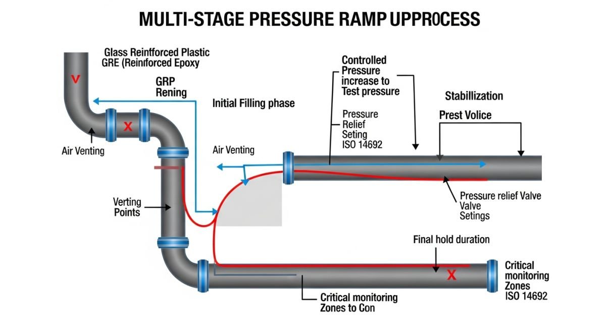
When performing a hydrostatic field test of GRP / GRE lines, the primary engineering challenge is managing the material’s response to internal pressure. Unlike steel, which has a defined yield point, GRP/GRE composites exhibit a complex stress-strain relationship influenced by the fiber orientation and the resin system’s glass transition temperature. My experience dictates that the pressurization sequence must be divided into distinct stages: initial filling, thermal stabilization, and the primary pressure hold.
Pressure Ramp Rate Control
The ramp rate is the most critical parameter. Rapid pressurization can induce “water hammer” effects or localized stress concentrations at fittings and flanges. According to AWWA M45, the pressure should be increased at a rate not exceeding 0.5 bar per minute for large-diameter lines. This slow progression allows the composite matrix to distribute the hoop stress evenly across the glass fiber reinforcement.
Field Warning: The “Creep” Factor
Do not mistake a pressure drop during the initial hold period for a leak. GRP and GRE materials undergo a phenomenon known as “initial creep” or “settling,” where the pipe diameter expands slightly under load. This volumetric increase causes a drop in pressure. Always allow for a 30-minute stabilization period before declaring a leak-free status.
Calculation of Test Pressure
The test pressure is typically defined as 1.5 times the rated operating pressure, but it must never exceed the manufacturer’s specified maximum allowable test pressure (MATP). The calculation follows the basic hoop stress formula, adjusted for the composite’s specific modulus of elasticity:
P_test = (2 * S * t) / (D – t)
Where S is the allowable stress for the specific resin/fiber combination, t is the wall thickness, and D is the outside diameter. In my practice, I always verify the S value against the ISO 14692 long-term hydrostatic strength (LTHS) data provided by the manufacturer. If the test pressure approaches 80% of the LTHS, the hold time must be strictly limited to prevent long-term fatigue degradation.
Composite Integrity Assessment: A comparative analysis of the operational benefits and technical limitations inherent in the hydrostatic testing of GRP and GRE piping systems.
Advantages
- Corrosion Immunity: Unlike metallic lines, GRP/GRE does not require internal lining inspection for corrosion-related wall thinning during the test.
- Weight Efficiency: Lower mass allows for easier temporary support during the test, reducing the need for heavy-duty shoring.
- Smooth Bore: The low friction coefficient ensures that pressure distribution is uniform throughout the test circuit.
- Predictable Failure: When properly designed, the failure mode is localized, allowing for easier identification of faulty joints.
Disadvantages
- Viscoelastic Sensitivity: The material’s tendency to creep makes it difficult to distinguish between a minor leak and material expansion.
- Thermal Expansion: High sensitivity to ambient temperature fluctuations requires strict control of test fluid temperature.
- Brittle Failure Risk: High-pressure testing carries a risk of explosive decompression if the pipe is damaged or improperly installed.
- Joint Sensitivity: Adhesive-bonded joints are highly sensitive to surface preparation, which can lead to “weeping” that is hard to detect.
Composite Piping Deployment: A summary of critical industrial sectors where GRP and GRE piping systems are utilized, necessitating rigorous hydrostatic field testing to ensure operational safety and environmental compliance.
Desalination Plant Intake Lines
Large-diameter GRP lines are the industry standard for seawater intake and brine discharge. These systems require extensive hydrostatic testing to ensure that the massive joints can withstand the cyclic loading of tidal forces and internal pressure surges.
Chemical Process Plant Infrastructure
GRE piping is frequently deployed in corrosive chemical transport where metallic pipes would fail within months. Hydrostatic testing here is critical to verify the integrity of the adhesive-bonded joints, which are the most common failure points in aggressive chemical environments.
Oil and Gas Produced Water Systems
In upstream oil and gas, GRE lines handle high-salinity produced water. The hydrostatic field test must account for the high operating temperatures of these fluids, requiring the test water to be heated to match the expected service temperature for accurate expansion data.
Municipal Water Transmission Networks
GRP piping is widely used for gravity and low-pressure water transmission. The hydrostatic test focuses on the integrity of the rubber-gasketed joints, ensuring that the seals remain tight under both positive pressure and potential vacuum conditions.
When executing a hydrostatic field test of GRP / GRE lines, the selection of test pressure is governed by the design pressure rating of the piping system and the specific requirements of the governing code, such as ISO 14692 or AWWA M45. Unlike metallic piping, which may undergo plastic deformation, composite materials exhibit linear elastic behavior up to the point of failure, making precise pressure control during the ramp-up phase critical to avoid micro-cracking of the resin matrix.
The following table outlines the standard pressure multipliers and hold durations typically encountered in industrial field applications. Engineers must ensure that the test pressure does not exceed the structural limit of the lowest-rated component in the test circuit, including flanges, valves, and expansion joints. Always verify the manufacturer’s specific pressure-temperature derating factors before finalizing the test manifold configuration.
| Test Parameter | Standard Multiplier | Recommended Duration |
|---|---|---|
| System Design Pressure | 1.0 x DP | Operational |
| Hydrostatic Test Pressure | 1.5 x DP | 1 to 4 Hours |
| Maximum Allowable Test | 1.1 x Rated | Short Duration |
The integrity of a composite piping system relies on the synergy between the fiber reinforcement and the chemical resistance of the resin matrix. During a hydrostatic field test of GRP / GRE lines, engineers must track specific physical parameters to ensure the structural health of the pipe remains within the elastic design envelope. This matrix maps the critical entities involved in the testing process, linking them to their respective industry standards and physical performance metrics.
By maintaining a clear mapping of these variables, site supervisors can effectively troubleshoot pressure drops or potential joint leakage. It is essential to note that GRP and GRE materials possess different thermal expansion coefficients compared to steel, which necessitates careful monitoring of ambient temperature fluctuations during the test hold period to prevent false pressure readings caused by fluid expansion or contraction.
| Entity | Standard Reference | Primary Function |
|---|---|---|
| Resin Matrix | ISO 14692 | Chemical resistance and load transfer |
| Fiber Reinforcement | ASTM D2996 | Tensile strength and structural rigidity |
| Joint Integrity | AWWA M45 | Leak prevention at connections |
Hydrostatic Field Test of GRP / GRE lines: Before initiating any pressure test, a comprehensive site verification is mandatory to ensure the safety of personnel and the integrity of the piping system. Composite materials are sensitive to improper support and thermal shock; therefore, the following checklist must be completed and signed off by the lead piping engineer.
- Verify that all pipe supports are fully installed and tightened to prevent movement during pressurization.
- Confirm that the test medium (usually water) is clean and free of debris that could damage internal liners.
- Ensure all high-point vents are open during filling to prevent air entrapment, which can cause dangerous pressure surges.
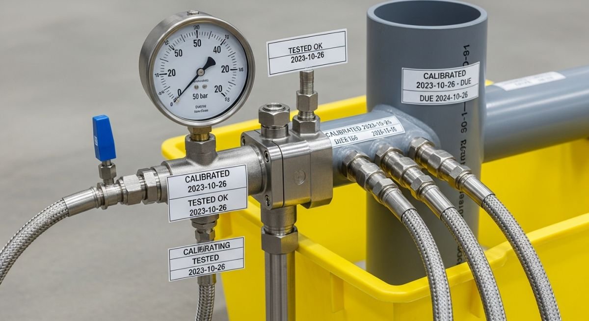
- Calibrate all pressure gauges to within 1% of the full-scale range per ASME B31.3 guidelines.
- Inspect all adhesive-bonded or laminated joints for complete curing before applying test pressure.
- Establish a clear exclusion zone around the test circuit to protect personnel from potential pipe failure.
Once these checks are verified, the pressure ramp-up should proceed in increments of 25% of the total test pressure. At each increment, hold the pressure for a minimum of 15 minutes to allow the composite material to stabilize. If any weeping or pressure decay is observed, immediately depressurize the system and perform a visual inspection of the affected joints or pipe sections.
Problem: Unexpected Pressure Decay in GRE Cooling Line
- Rapid pressure loss observed during the final 30 minutes of a 4-hour hold test.
- Inadequate curing time allowed for the field-fabricated adhesive joints.
- Thermal expansion caused by direct sunlight exposure on the uninsulated pipe.
- Vibration from nearby heavy machinery affecting the integrity of the temporary test manifold.
Outcome: Successful Remediation and Certification
- Re-curing of joints performed under controlled temperature conditions.
- Installation of temporary sunshades to mitigate thermal expansion effects.
- Successful re-test with zero pressure drop over the required 4-hour duration.
- Implementation of a mandatory 24-hour cure-time protocol for all future field joints.
In my experience, the primary cause of failure in these scenarios is often the rush to complete the test before the adhesive has fully cross-linked. Always prioritize the manufacturer’s curing schedule over the project timeline to ensure long-term system reliability.
Frequently Asked Engineering Questions
Why is air removal critical for GRP testing?
- Air pockets prevent accurate pressure monitoring, leading to false test results.
- Rapid expansion of air during a leak can cause shock waves that damage the brittle resin matrix.
- Always ensure high-point vents are positioned correctly to facilitate complete air evacuation before pressurization.
How do temperature fluctuations affect test results?
- Monitor ambient temperature throughout the test duration to correlate pressure changes.
- Use insulated test manifolds if testing in environments with high diurnal temperature swings.
- Consult ISO 14692 for guidance on acceptable pressure variations due to thermal effects.
What is the maximum ramp rate for GRP?
- Limit the pressure increase to a maximum of 25% of the test pressure per increment.
- Allow for a stabilization period of at least 15 minutes between each increment.
- Avoid sudden valve operations that could cause water hammer effects within the system.
Are there specific requirements for test gauges?
- Ensure all gauges are calibrated within the last 6 months.
- Use dual gauges at different locations to verify pressure uniformity across the test circuit.
- Digital pressure transducers are preferred for their ability to log data and detect minute pressure fluctuations.
How to handle joint weeping during testing?
- Depressurize the system completely before performing any repairs.
- Inspect the joint for signs of improper surface preparation or insufficient adhesive application.
- Re-test the system only after the repair has fully cured according to the manufacturer’s specifications.
What documentation is required post-test?
- Include the test pressure, duration, and ambient temperature logs.
- Attach calibration certificates for all pressure gauges used during the test.
- Document any anomalies or repairs performed during the testing process, signed by the authorized inspector.
📚 Recommended Resources: Hydrostatic Field Test of GRP / GRE
Complete Course on
Piping Engineering
Check Now
Key Features
- 125+ Hours Content
- 500+ Recorded Lectures
- 20+ Years Exp.
- Lifetime Access
Coverage
- Codes & Standards
- Layouts & Design
- Material Eng.
- Stress Analysis
