Table of Contents
H-beam vs I-beam: Structural Differences and Engineering Selection Guide
Over my 20 years in structural and piping design, I have seen countless project delays because a junior engineer specified an I-beam where an H-beam was structurally mandatory. At first glance, these two structural steel profiles look almost identical. However, when you subject them to heavy axial loads or lateral bending forces, their mechanical behaviors diverge dramatically. Choosing the wrong profile can lead to excessive deflection, lateral torsional buckling, or catastrophic structural failure.
In this guide, I will break down the fundamental differences between H-beams and I-beams. We will look at their cross-sectional geometries, mechanical properties, and load-bearing capacities. I will also share a comprehensive size chart and the exact engineering formulas I use to verify these profiles on the job site.
Key Engineering Takeaways
- H-beams feature wider flanges and equal web-to-flange thickness, making them ideal for columns and axial compression.
- I-beams have tapered flanges and thinner webs, optimizing them for vertical bending loads where lateral buckling is restrained.
- The radius of gyration about the weak axis is significantly larger in H-beams, providing superior resistance to buckling.
- Standard specifications are governed by AISC 360 and ASTM A6 standards.
- Welded H-beams offer custom dimensioning, whereas I-beams are almost exclusively hot-rolled.
Understanding H-beam vs I-beam Structural Profiles
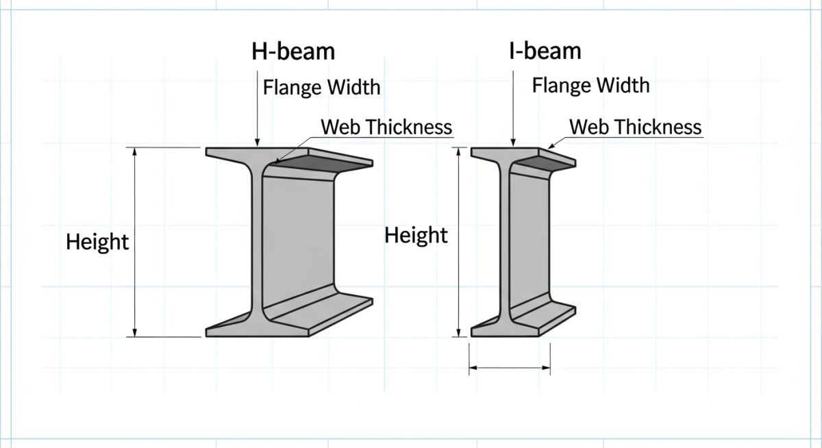
To understand why these beams perform so differently, we must analyze their cross-sectional geometry. An H-beam is often called a “wide flange” beam. Its flange width is roughly equal to its depth, creating a square-like profile. This geometry distributes material away from the neutral axis in both directions, which increases the moment of inertia about both the strong axis (x-axis) and the weak axis (y-axis).
Conversely, an I-beam has a much narrower flange relative to its depth. The inner surfaces of the flanges are tapered, usually at a slope of 1:10 or 1:6, depending on the standard. This concentration of material along the vertical centerline makes the I-beam highly efficient at resisting vertical bending, but highly susceptible to lateral torsional buckling if it is not laterally braced.
Mechanical Calculations and Stress Parameters
When I design structural supports, I rely on three primary mechanical parameters: bending stress, shear stress, and the radius of gyration. Let us look at how these are calculated.
1. Bending Stress (Sigma):
Bending Stress = M / S
Where M is the applied bending moment and S is the section modulus (S = I / y). Because H-beams have a larger section modulus about both axes, they handle multi-directional bending far better than I-beams.
2. Shear Stress (Tau):
Shear Stress = (V * Q) / (I * t)
Where V is the shear force, Q is the first moment of area, I is the moment of inertia, and t is the web thickness. In an I-beam, the thin web carries almost all the vertical shear force, making web shear failure a critical design limit state under AISC 360 Chapter G.
3. Radius of Gyration (r):
Radius of Gyration = Square Root of (I / A)
Where I is the moment of inertia and A is the cross-sectional area. The radius of gyration determines the slenderness ratio (L/r) of a column. A higher r value prevents buckling. An H-beam has a much larger r-y (weak-axis radius of gyration) than an I-beam, which is why H-beams are the industry standard for columns.
Key Engineering Differences in H-beam vs I-beam
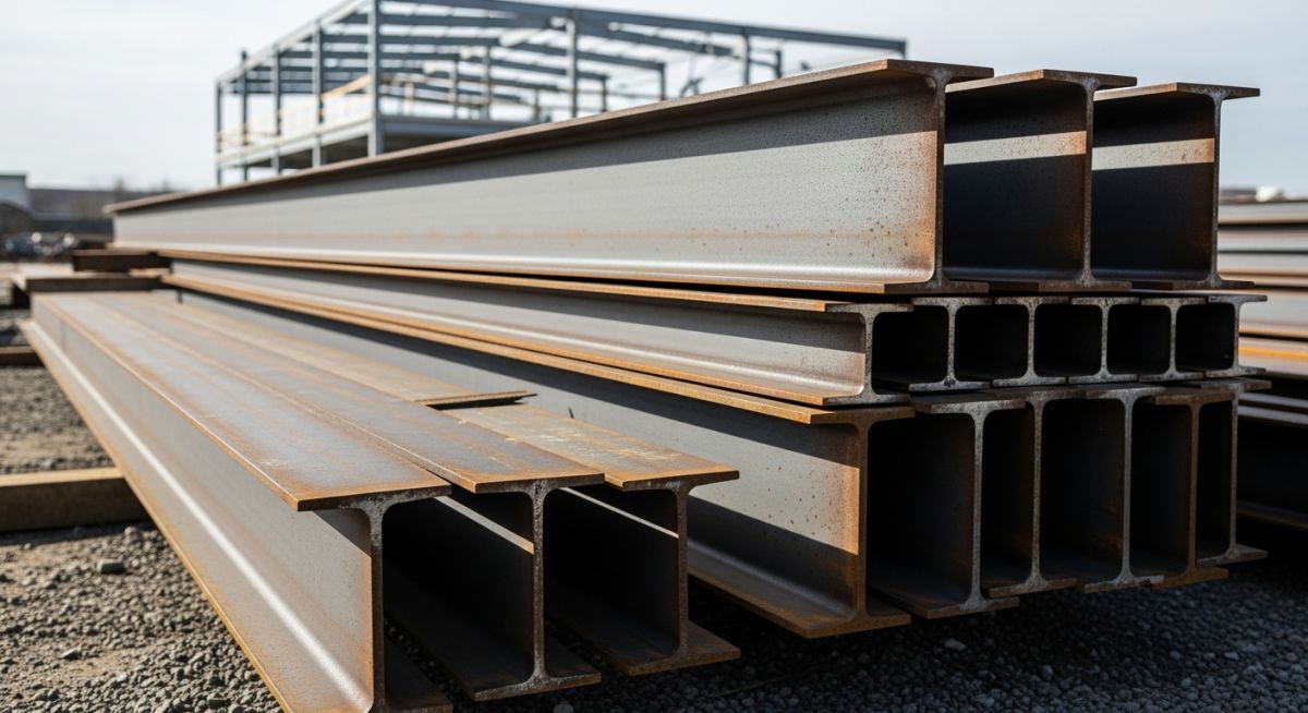
In my field experience, the choice between these two profiles often comes down to fabrication limits and span lengths. H-beams can be rolled up to massive sizes, or they can be custom-fabricated by welding three separate steel plates together. This is highly beneficial for heavy industrial structures where standard rolled sections cannot meet the load requirements.
I-beams, on the other hand, are almost always hot-rolled as a single piece of steel. This makes them lighter and more cost-effective for shorter spans with clear, unidirectional loads, such as overhead crane runways or floor joists. However, because their flanges are narrow, they cannot handle significant torsional (twisting) forces. If your structure is subjected to eccentric loading, an I-beam will twist and fail rapidly unless it is heavily braced.
Standard Dimensions and Sectional Properties
Below is a comparative size chart showing standard European and American profiles. This data is critical for calculating bending moments and deflection limits during the initial design phase.
| Profile Type | Designation | Depth (mm) | Flange Width (mm) | Web Thickness (mm) | Flange Thickness (mm) | Weight (kg/m) |
|---|---|---|---|---|---|---|
| H-Beam (HEB) | HEB 100 | 100 | 100 | 6.0 | 10.0 | 20.4 |
| H-Beam (HEB) | HEB 200 | 200 | 200 | 9.0 | 15.0 | 61.3 |
| H-Beam (HEB) | HEB 300 | 300 | 300 | 11.0 | 19.0 | 117.0 |
| I-Beam (IPE) | IPE 100 | 100 | 55 | 4.1 | 5.7 | 8.1 |
| I-Beam (IPE) | IPE 200 | 200 | 100 | 5.6 | 8.5 | 22.4 |
| I-Beam (IPE) | IPE 300 | 300 | 150 | 7.1 | 10.7 | 42.2 |
This matrix maps the core technical entities, structural acronyms, and physical parameters to their respective design standards.
| Parameter / Entity | Acronym | Primary Application | Governing Standard |
|---|---|---|---|
| Wide Flange Beam | W-Shape / HEB | Columns, heavy load-bearing frames | ASTM A992 / EN 10025 |
| Standard I-Beam | S-Shape / IPE | Floor joists, light platforms, monorails | ASTM A36 / EN 10025 |
| Lateral Torsional Buckling | LTB | Limit state design for unbraced beams | AISC 360 Chapter F |
| Mill Test Certificate | MTC | Material traceability and quality assurance | EN 10204 Type 3.1 |
Field Verification and Quality Control Protocols
When structural steel arrives on-site, you cannot simply trust the delivery slip. I have personally rejected entire shipments of steel because the flange thickness did not match the design drawings. Below is the exact checklist I use during field inspections to ensure structural integrity.
On-Site Structural Steel Inspection Checklist
-
Measure Flange and Web Dimensions: Use a calibrated digital caliper to measure flange width, flange thickness, and web thickness. Compare these against the tolerances specified in ASTM A6.
-
Inspect for Sweep and Camber: Check the straightness of the beam along its longitudinal axis. Excessive sweep (horizontal curvature) or camber (vertical curvature) can make installation impossible and introduce unintended eccentric loads.
-
Examine Weld Quality (for Welded H-beams): If using built-up welded H-beams, verify that the web-to-flange fillet welds have been inspected using Non-Destructive Testing (NDT) such as Magnetic Particle Testing (MT) or Ultrasonic Testing (UT) per AWS D1.1.
-
Check Surface Preparation and Coating: Ensure the primer thickness (DFT) matches the specification, especially in highly corrosive environments like chemical plants or offshore platforms.
Field Case Study: Real-World Application
My direct recommendation from this project is clear: always use H-beams for columns and primary structural frames subjected to lateral or multi-directional loads. Reserve I-beams strictly for secondary horizontal members where the compression flange is continuously braced by concrete decking or grating.
Frequently Asked Engineering Questions
1. Can I use an I-beam as a vertical column?
2. Why are H-beams heavier than I-beams?
3. What is the standard steel grade for these beams?
4. How does flange taper affect connection design?
5. Can welded H-beams replace hot-rolled H-beams?
6. Which beam profile is more cost-effective for long spans?
Complete Course on
Piping Engineering
Check Now
Key Features
- 125+ Hours Content
- 500+ Recorded Lectures
- 20+ Years Exp.
- Lifetime Access
Coverage
- Codes & Standards
- Layouts & Design
- Material Eng.
- Stress Analysis

📚 Recommended Resources: H-beam vs I-beam
Read these Guides
Related posts:
![A mechanical sucker rod pumpjack operating in an oil field at sunset]()
What is Sucker Rod Pump System in Oil Production?
![Piping material engineer reviewing technical specifications on a tablet in an industrial plant.]()
How a Piping Material Engineer Drives Industrial Project Success
![Industrial refinery plant showing various types of static equipment]()
What is Static Equipment? Types and List of Static Equipments
![Side-by-side comparison of industrial process piping and power plant steam piping systems.]()
Differences Between ASME B31.3 and B31.1: B31.3 vs B31.1
![Large industrial steel storage tank under construction with cranes and scaffolding]()
Storage Tank Construction Method Statement: Step-by-Step Engineering Guide
![Cutaway diagram of a globe control valve highlighting the internal valve trim components]()
What is a Valve Trim? Types, Components, and Selection


