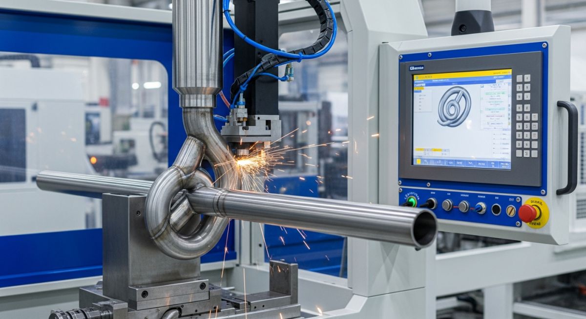
What Are Tube Benders? Types, Components, and Selection Guide
In my 20-plus years of managing piping systems in petrochemical plants and offshore platforms, I have seen millions of dollars wasted because of a simple, overlooked detail: a poorly executed tube bend. Many engineers treat tubing as a minor utility, but when you are running high-pressure hydraulic lines or volatile chemical feeds, the integrity of every single bend is just as critical as a primary structural weld.
Using the wrong bending method or failing to account for material springback can lead to microcracking, excessive wall thinning, or ovality that restricts flow and invites fatigue failure. This guide is written from the perspective of the shop floor and the engineering office, detailing how to select, operate, and verify the performance of industrial tube benders to ensure code compliance and long-term system reliability.
Key Engineering Takeaways
- Understand the physical mechanics of plastic deformation to prevent wall thinning at the extrados and wrinkling at the intrados.
- Identify the five core tooling components of a rotary draw bender and how their alignment directly impacts bend quality.
- Apply ASME B31.3 code formulas to calculate minimum wall thickness requirements after bending.
- Select the correct bending method (rotary draw, roll, compression, or press) based on production volume and geometric tolerances.
How Do Industrial Tube Benders Actually Work?
To understand tube bending, we must look at the stress distribution across the tube cross-section during deformation. When a tube is bent, the material on the outer radius of the bend (the extrados) is subjected to tensile stress, causing it to stretch and thin out. Conversely, the material on the inner radius (the intrados) experiences compressive stress, which causes it to thicken and, if unsupported, wrinkle.
Between these two zones lies the neutral axis. As bending progresses, this neutral axis shifts inward toward the intrados. This shift increases the tensile forces on the extrados, making the tube highly susceptible to flattening (ovality) and cracking. To combat these forces, industrial tube benders utilize a combination of internal and external tooling to support the tube walls.
The Five Core Tooling Components
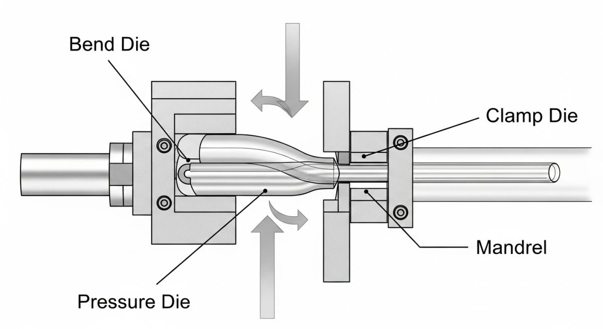
In high-precision rotary draw bending, five distinct tooling elements work in unison to control material flow:
- 1. Bend Die (Center Former): The primary die around which the tube is wrapped. It establishes the Center Line Radius (CLR) of the bend.
- 2. Clamp Die: Presses the tube against the bend die, locking it in place so that as the bend die rotates, the tube is drawn along with it.
- 3. Pressure Die: Follows the tube as it is drawn, providing the necessary reaction force to push the tube into the bend die and maintain alignment.
- 4. Mandrel: An internal support insert (often segmented or ball-type) positioned inside the tube at the point of bend. It prevents the tube from collapsing or flattening.
- 5. Wiper Die: Positioned on the intrados side just before the tangent point. It wipes the material to prevent wrinkles from forming as the tube is compressed.
ASME B31.3 Wall Thickness Calculations
As an engineer, you cannot simply bend a tube and assume it will hold the design pressure. ASME B31.3 Section 304.2.1 requires that the wall thickness of a bend, after bending, must be sufficient to withstand internal design pressure. The minimum required thickness at the intrados and extrados is calculated using the bend thinning factor (I):
Where:
- P: Internal design gage pressure.
- D: Outside diameter of the tube.
- S: Allowable stress value for the material at design temperature.
- E: Quality factor.
- W: Weld joint strength reduction factor.
- Y: Coefficient from Table 304.1.1.
- I: Bend thinning factor, calculated separately for the intrados and extrados.
The intrados factor (I_in) and extrados factor (I_out) are determined by the ratio of the bend radius (R) to the tube outside diameter (D):
I_out = (4 * (R / D) + 1) / (4 * (R / D) + 2)
Because I_in is always greater than 1.0, the required thickness at the intrados is always greater than that of a straight pipe. Conversely, because I_out is less than 1.0, the required thickness at the extrados is technically lower, but the physical thinning that occurs during bending usually offsets this, requiring a thicker starting tube.
In my field audits, I frequently find operators placing the mandrel too far back from the tangent point. If the mandrel tip does not extend slightly past the tangent point of the bend, the tube will collapse, leading to severe ovality. Furthermore, always account for material springback. Stainless steel can spring back by 2 to 5 degrees, requiring the machine to overbend the tube to achieve the target angle.
Standard Tooling and Bending Limits
Selecting the correct bending method depends heavily on the tube’s wall factor (Outside Diameter divided by Wall Thickness) and the bend ratio (Center Line Radius divided by Outside Diameter). The table below outlines the standard limits for different bending methods.
| Bending Method | Min Bend Radius (CLR) | Typical Wall Factor Range | Mandrel Required? | Wiper Die Required? |
|---|---|---|---|---|
| Rotary Draw (Standard) | 1.5D to 3D | 10 to 30 | Only for thin walls | Rarely |
| Rotary Draw (Mandrel) | 1.0D to 2.0D | 30 to 100+ | Yes (Mandrel) | Yes (For Wall Factor > 40) |
| Compression Bending | 3D to 5D | Under 20 | No | No |
| Roll Bending (3-Roll) | 6D and above | Under 30 | No | No |
| Press Bending | 3D to 6D | Under 15 | No | No |
Technical Mapping & Specifications Matrix
| Material Grade | Applicable Standard | Max Allowable Ovality | Max Allowable Thinning | Recommended Lubricant |
|---|---|---|---|---|
| 316/316L Stainless Steel | ASTM A269 / ASME B31.3 | 8% (Process) / 3% (High-Pressure) | 12.5% of nominal wall | High-viscosity synthetic gel |
| Carbon Steel (A106 Gr. B) | ASTM A106 / ASME B31.1 | 8% (Power Piping) | 10% of nominal wall | Heavy-duty chlorinated oil |
| Copper (C12200) | ASTM B75 / ASME B31.5 | 10% (Refrigeration) | 15% of nominal wall | Water-soluble synthetic oil |
| Titanium (Grade 2) | ASTM B338 / Aerospace Specs | 5% (Critical Systems) | 10% of nominal wall | Paste-type extreme pressure lubricant |
Pre-Bending Quality Control Checklist
Before initiating any bending run on the shop floor, the quality control inspector and machine operator must verify the following parameters. Skipping even one of these steps can result in a rejected batch of tubing or, worse, a catastrophic field failure.
Mandatory Verification Steps
-
Material Traceability: Verify that the tube heat number matches the Material Test Report (MTR) and conforms to the specified ASTM/ASME standard.
-
Dimensional Verification: Measure the actual Outside Diameter (OD) and Wall Thickness (WT) using calibrated micrometers. Do not rely solely on nominal dimensions.
-
Tooling Alignment: Ensure the wiper die is set at the correct angle (typically 1 to 2 degrees relative to the bend die) and that the mandrel is positioned slightly past the tangent point.
-
Lubrication Application: Confirm that the internal mandrel lubricant is applied evenly and is compatible with the tube material (e.g., chlorine-free lubricants for stainless steel to prevent stress corrosion cracking).
-
Springback Calibration: Run a test bend on a scrap piece of the same heat batch to measure actual springback and program the CNC controller accordingly.
Field Case Study: Real-World Application
The Problem: High-Pressure Hydraulic Line Failures
During the commissioning of an offshore drilling rig’s hydraulic control system, several 1.5-inch OD x 0.083-inch WT 316L stainless steel tubes failed during hydrostatic testing at 4,500 psi. The failures occurred consistently at the extrados of 90-degree bends.
Upon inspection, I discovered that the fabrication shop had used a manual press bender without an internal mandrel. This resulted in severe ovality (measured at 11.2%, exceeding the 8% limit) and localized wall thinning at the extrados down to 0.062 inches. This thinning reduced the pressure-containing capability of the tube below the safe operating limit, causing ductile rupture under test pressure.
The Solution & Outcome
I immediately halted fabrication and mandated the transition to a CNC rotary draw bender equipped with a multi-ball mandrel and a bronze-alloy wiper die. We recalculated the minimum wall thickness using ASME B31.3 formulas and established a strict tooling setup protocol.
By utilizing the mandrel to support the inner tube wall and the wiper die to prevent wrinkling, we achieved highly consistent bends. The post-bend inspection showed that ovality was reduced to an average of 2.1%, and wall thinning at the extrados was limited to 9.4% (retaining a safe wall thickness of 0.075 inches). The newly fabricated lines passed the hydrostatic test with zero failures, saving the project from costly operational delays.
How to Select the Right Tube Benders
Selecting the right equipment requires a deep understanding of your material properties and production requirements. Below are the most common questions I encounter in the field regarding tube bender selection and operation.
What is the difference between tube bending and pipe bending?
When is a mandrel necessary in tube bending?
How does springback affect the tube bending process?
What causes wrinkling on the inside of a bend?
How is wall thinning calculated and controlled?
Which standards govern industrial tube bending quality?
Complete Course on
Piping Engineering
Check Now
Key Features
- 125+ Hours Content
- 500+ Recorded Lectures
- 20+ Years Exp.
- Lifetime Access
Coverage
- Codes & Standards
- Layouts & Design
- Material Eng.
- Stress Analysis