Copper Pipes and Tubes: Engineering Guide to Types, Sizes, and Applications
In my 20+ years of piping engineering experience, I have seen materials come and go, but copper remains an absolute workhorse in commercial plumbing, HVAC, and medical gas distribution. When designing these systems, selecting the correct wall thickness and temper is not just a matter of cost—it is a critical safety and longevity decision. A misapplied thin-walled tube in a high-pressure or corrosive environment can lead to catastrophic pinhole leaks, water hammer failures, or velocity-induced erosion.
This guide draws directly from my field experience and the governing standards of the American Society for Testing and Materials (ASTM) and the American Society of Mechanical Engineers (ASME). We will dissect the physical differences between Type K, L, and M copper, walk through the exact pressure rating calculations, and establish clear field verification protocols to ensure your installations stand the test of time.
Key Engineering Takeaways
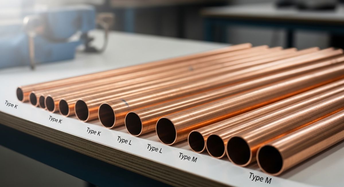
- Wall Thickness Hierarchy: Type K has the thickest wall, followed by Type L (medium), and Type M (thinnest).
- Governing Standards: ASTM B88 governs seamless copper water tube, while ASTM B306 covers copper drainage tube (DWV).
- Velocity Limits: To prevent erosion-corrosion, limit cold water velocity to 5-8 feet per second (fps) and hot water to 3-4 fps.
- Joining Methods: Soldering, brazing, and mechanical press-connect systems each have distinct pressure-temperature derating factors.
Understanding Copper Pipes and Tubes Specifications
When we specify copper tubing, we must first distinguish between “nominal” size (used for plumbing and water distribution) and “actual outside diameter” (often used in air conditioning and refrigeration, referred to as ACR tubing). For plumbing tubes under ASTM B88, the actual outside diameter (OD) is always exactly 1/8 inch (0.125 inches) larger than the nominal size. For example, a 1-inch nominal copper pipe has an actual OD of 1.125 inches.
The Three Primary Types: K, L, and M
The wall thickness of the tube determines its classification. Because the outside diameter remains constant for a given nominal size to allow the use of standardized fittings, the internal diameter (ID) varies depending on the type:
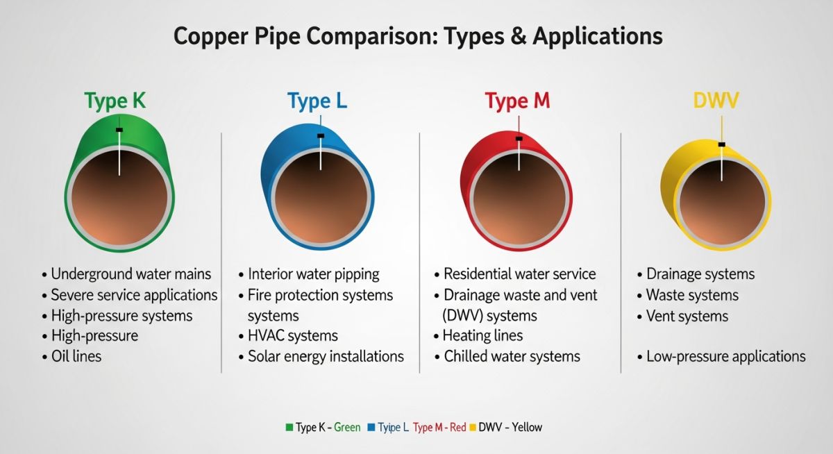
- Type K (Thick-Walled): Typically specified for underground service lines, water mains, and heavy-duty industrial applications where external soil loads and harsh environments are present. It is available in both drawn (hard) tempers and annealed (soft) coils.
- Type L (Medium-Walled): The most versatile and widely specified type for interior domestic water distribution, fire protection systems, and hydronic heating loops. It offers an optimal balance between pressure capacity and material cost.
- Type M (Thin-Walled): Primarily used for low-pressure domestic water lines, vacuum systems, and non-critical gravity heating systems. Many municipal codes restrict its use to visible, above-ground installations due to its susceptibility to mechanical damage and corrosion.
Engineering Calculations: Hydrostatic Pressure Ratings
To determine the safe working pressure of a copper tube, we utilize the modified Barlow’s Formula as specified in ASME B31.9 (Building Services Piping). The formula calculates the internal design pressure based on the allowable stress of the material at a specific operating temperature:
Where:
P = Maximum allowable working pressure (psi)
S = Allowable stress of the copper material (psi)
t = Minimum wall thickness of the tube (inches)
D = Outside diameter of the tube (inches)
Let us perform a practical calculation for a 2-inch Nominal Type L copper tube (drawn temper) operating at a temperature of 150°F (65°C).
- Identify Dimensions: For 2-inch nominal Type L, the Outside Diameter (D) is 2.125 inches, and the nominal wall thickness is 0.070 inches. Accounting for a standard 10% manufacturing tolerance, the minimum wall thickness (t) is 0.063 inches.
- Determine Allowable Stress (S): According to ASME B31.9, the allowable stress for drawn copper tube (ASTM B88) at 150°F is 10,300 psi.
- Apply the Formula:
P = (2 * 10,300 * 0.063) / (2.125 – 0.8 * 0.063)
P = 1,297.8 / (2.125 – 0.0504)
P = 1,297.8 / 2.0746 ≈ 625.5 psi
This calculation yields the raw structural capacity of the tube itself. However, in practice, the joint efficiency factor of the connection method (soldered, brazed, or pressed) will significantly reduce this rating. For instance, a soft-soldered joint using 50-50 Tin-Lead or Lead-Free solder drops the allowable system pressure of this same 2-inch line down to approximately 150 psi at 150°F.
The table below provides the standard dimensions, weights, and allowable working pressures for ASTM B88 seamless copper water tubes. These values are calculated for drawn (hard) temper tubes at an operating temperature of 100°F (38°C) using the ASME B31.9 design criteria.
| Nominal Size (in) | Actual OD (in) | Type K Wall (in) | Type K Pressure (psi) | Type L Wall (in) | Type L Pressure (psi) | Type M Wall (in) | Type M Pressure (psi) |
|---|---|---|---|---|---|---|---|
| 1/2 | 0.625 | 0.049 | 1,450 | 0.040 | 1,150 | 0.028 | 800 |
| 3/4 | 0.875 | 0.065 | 1,350 | 0.045 | 900 | 0.032 | 650 |
| 1 | 1.125 | 0.065 | 1,000 | 0.050 | 750 | 0.035 | 550 |
| 1-1/2 | 1.625 | 0.072 | 750 | 0.060 | 620 | 0.049 | 500 |
| 2 | 2.125 | 0.083 | 680 | 0.070 | 550 | 0.058 | 450 |
This matrix maps specific copper alloys, standards, and joining methods to their approved industrial applications and temperature limits.
| Material Standard | Alloy Designation | Primary Applications | Approved Joining Methods | Max Temp Limit |
|---|---|---|---|---|
| ASTM B88 | C12200 (DHP Copper) | Potable Water, Hydronic Heating | Soldering, Brazing, Press-Fit | 400°F (204°C) |
| ASTM B280 | C12200 (Deoxidized High Phosphorous) | Air Conditioning & Refrigeration (ACR) | Brazing, Flare Fittings | 300°F (149°C) |
| ASTM B306 | C12200 | Drain, Waste, & Vent (DWV) | Soldering | 150°F (66°C) |
| ASTM B819 | C12200 (Cleaned & Capped) | Medical Gas Systems (O2, N2O, Vacuum) | Brazing (with Nitrogen Purge) | 200°F (93°C) |
Site Inspection Checklist for Copper Piping
In my role as a lead quality auditor, I have found that over 80% of premature copper piping failures stem from poor installation practices rather than material defects. Use this checklist on-site to verify that your copper installations comply with engineering specifications and industry standards.
Field Quality Control Checkpoints
-
Material Identification: Verify that the continuous color-coded stripe on the tube matches the specification (Green for Type K, Blue for Type L, Red for Type M, Yellow for DWV).
-
Deburring and Reaming: Ensure all cut pipe ends are fully reamed to their full internal diameter. Unreamed ends create localized turbulence, leading to rapid erosion-corrosion downstream.
-
Hanger Spacing and Isolation: Confirm that horizontal support spacing complies with MSS SP-58 (e.g., maximum 8-foot spacing for 1-inch and smaller tubes). Ensure copper-plated or plastic-coated hangers are used to prevent galvanic corrosion from contact with dissimilar metals.
-
Brazing Purge: For medical gas (ASTM B819) and refrigeration lines, verify that a continuous nitrogen purge is maintained during brazing to prevent the formation of copper oxide scale inside the tube.
-
Flux Removal: Inspect soldered joints to ensure all residual chemical flux has been wiped clean from the exterior of the pipe. Acidic flux residues will corrode the copper over time.
Field Case Study: Real-World Application
The Problem: Systemic Pinhole Leaks in a Hospital Hot Water Loop
A major regional hospital experienced repeated pinhole leaks in its 2-inch domestic hot water recirculation loop just four years after construction. The maintenance team had already clamped twelve separate leaks, and the facility was facing potential water damage in critical patient care areas.
Upon site investigation, I discovered two major design and installation errors. First, the contractor had installed Type M copper instead of the specified Type L. Second, the recirculation pump was oversized, running continuously and generating water velocities of 7.2 feet per second at an operating temperature of 145°F (63°C).
The Outcome: Remediation and Velocity Control
We executed a multi-step remediation plan. First, we replaced the entire compromised run with ASTM B88 Type L drawn copper tubing. Second, we replaced the oversized constant-speed pump with a variable-frequency drive (VFD) pump controlled by a temperature sensor.
By programming the pump to maintain a maximum velocity of 3.5 feet per second and lowering the loop temperature to 130°F (54°C) during low-demand hours, we eliminated the turbulent shear stress on the inner pipe wall. Follow-up ultrasonic thickness testing after two years of operation showed zero measurable wall loss.
My direct recommendation for any hot water recirculation system is to strictly enforce a maximum velocity limit of 4.0 feet per second for copper piping, and to always specify Type L or Type K copper. Type M should never be permitted in continuous-flow, heated applications.
FAQs Regarding Copper Pipes and Tubes
What is the primary difference between Type K, L, and M copper?
Can Type M copper be used for underground water service lines?
How does temperature affect the pressure rating of copper tubes?
What causes erosion-corrosion in copper piping systems?
Why must nitrogen be purged through copper lines during brazing?
What is the difference between ASTM B88 and ASTM B280 tubing?
===
Complete Course on
Piping Engineering
Check Now
Key Features
- 125+ Hours Content
- 500+ Recorded Lectures
- 20+ Years Exp.
- Lifetime Access
Coverage
- Codes & Standards
- Layouts & Design
- Material Eng.
- Stress Analysis

📚 Recommended Resources: copper pipes and tubes
Related posts:
![3D engineering visualization of a piping system undergoing thermal expansion with stress concentration points highlighted in red and yellow.]()
Piping Flexibility Analysis: Essential Requirements for Safe Industrial Design
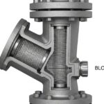
![Industrial Y-type piping strainer installed in a high-pressure steel pipeline with visible flanged connections and blow-off valve.]()
Piping Strainers: Design Standards, Selection Criteria, and Industrial Applications
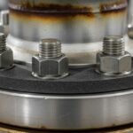
![Industrial flange connection with high-strength alloy steel studs and nuts in a refinery piping system.]()
How to Select a Bolt: The Complete Engineering Selection Process
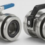
![Close-up view of industrial Elaflex and Todo hose couplings showing locking mechanisms and stainless steel construction for chemical transfer.]()
Industrial Hose Couplings: Elaflex and Todo Coupling Design Guide
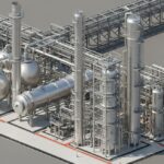
![3D isometric plot plan showing the strategic placement of reactors, fired heaters, and pressure vessels in a refinery.]()
Strategic Location of Static Equipment: Fired Heaters, Reactors, and Drums
![Professional welder performing high-precision field welding on industrial piping in a refinery construction site.]()
General Requirements for Field Welding: A Piping Engineering Guide