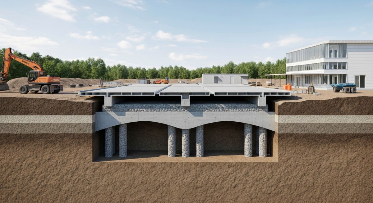
Ground Improvement for Data Centres: Ensuring Structural Integrity
In my two decades of experience, I have observed that the most common failure point for modern data centres is not the server hardware, but the foundation beneath it. Data centres impose massive, concentrated static loads that demand near-zero tolerance for differential settlement. When we encounter soft, compressible, or loose soils, traditional shallow foundations are rarely sufficient.
Ground improvement for data centres is a critical engineering phase that transforms marginal land into a stable platform. By utilizing techniques like vibro-compaction or deep soil mixing, we can effectively densify the soil matrix, reducing the risk of liquefaction and long-term creep. This guide explores the technical methodologies required to meet the stringent geotechnical requirements of mission-critical facilities.
Key Takeaways for Engineers:
- Differential settlement must be limited to prevent structural stress on sensitive server racks.
- Soil densification techniques must be validated through rigorous Cone Penetration Testing (CPT).
- Selection of the improvement method depends on the soil’s grain size distribution and moisture content.
- Long-term performance monitoring is mandatory for high-load, high-value infrastructure.
Technical Deep-Dive: Ground Improvement for Data Centres
Ground Improvement for Data Centres: The application of geotechnical engineering principles to enhance the mechanical properties of soil, specifically targeting shear strength, stiffness, and permeability to support heavy, vibration-sensitive equipment.
When designing foundations for data centres, we must account for the high intensity of floor loads, often exceeding 20 to 30 kPa. The primary challenge is mitigating differential settlement, which can cause misalignment in server racks and cooling infrastructure. In my experience, the selection of a ground improvement strategy is dictated by the soil’s relative density and the presence of fines.
Vibro Compaction and Stone Columns
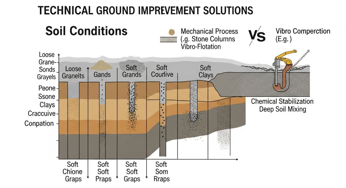
Vibro-compaction is highly effective in granular soils with less than 15% fines. By inserting a vibrating probe, we induce liquefaction-like conditions, allowing the soil particles to rearrange into a denser state. For soils with higher silt or clay content, we transition to stone column installation (vibro-replacement). This creates stiff inclusions that act as vertical drains and load-bearing elements.
Field Warning: Soil Fines Content
Always verify the fines content (particles smaller than 0.075 mm) before selecting vibro-compaction. If the fines content exceeds 15-20%, the soil will not densify effectively under vibration, and you must pivot to deep soil mixing or rigid inclusions to achieve the required bearing capacity.
Deep Soil Mixing (DSM)
Deep Soil Mixing involves the mechanical blending of in-situ soil with a binder, typically cement or lime. This creates soil-cement columns that significantly increase the shear strength of soft clays. The design must account for the unconfined compressive strength (UCS) of the soil-binder mix, which is typically verified through laboratory mix designs before full-scale implementation.
For data centre projects, I recommend a minimum UCS of 1.0 to 2.0 MPa for the soil-cement columns. The spacing of these columns is determined by the tributary area of the foundation load and the allowable settlement criteria, often calculated using the finite element method (FEM) to model the interaction between the columns and the surrounding soil matrix.
Engineering Trade-offs: The evaluation of ground improvement techniques requires balancing cost, schedule, and long-term structural performance against the specific geotechnical constraints of the site.
Advantages
- Significant reduction in total and differential settlement.
- Increased bearing capacity allows for shallower, more economical foundation designs.
- Mitigation of liquefaction risk in seismic-prone regions.
- Faster construction timelines compared to deep pile foundations.
- Lower environmental impact due to reduced material transport and excavation.
Disadvantages
- High sensitivity to soil composition; requires extensive pre-construction testing.
- Quality control is difficult to verify without advanced instrumentation.
- Potential for vibration-induced damage to adjacent existing structures.
- Limited effectiveness in highly organic or peat-rich soil deposits.
- Requires specialized equipment and highly skilled operators for success.
Geotechnical Implementation Scenarios: Ground improvement is applied across various industrial sectors to ensure that heavy infrastructure remains stable on challenging terrain.
Hyperscale Data Centre Foundations
In hyperscale facilities, the sheer weight of server racks and cooling systems requires a uniform, high-stiffness subgrade. We utilize stone columns to bridge soft layers, ensuring that the floor slab remains perfectly level to prevent micro-vibrations that could disrupt sensitive server hardware.
Coastal Infrastructure Stabilization
Data centres located in coastal regions often face loose, saturated sands prone to liquefaction. Deep soil mixing is deployed here to create a rigid, impermeable block that not only increases bearing capacity but also acts as a barrier against groundwater infiltration and lateral soil movement.
Brownfield Site Redevelopment
When repurposing industrial brownfields, we often encounter heterogeneous fill materials that are unsuitable for direct loading. Dynamic compaction is frequently used to densify these variable layers, creating a consistent foundation platform that meets the stringent requirements for modern, high-density data centre construction.
Selecting the appropriate ground improvement technique for a mission-critical data centre requires a rigorous evaluation of soil mechanics, site-specific loading conditions, and allowable settlement tolerances. Because data centres house sensitive server racks and high-density power infrastructure, the differential settlement criteria are significantly more stringent than those for standard commercial warehouses or industrial facilities.
The following table summarizes the primary performance indicators for common ground improvement methods. These parameters are derived from ASCE and ASTM standards, focusing on the effective depth of treatment and the resulting improvement in bearing capacity. Engineers must verify these values against site-specific borehole logs and cone penetration test (CPT) data before finalizing the foundation design.
| Method | Effective Depth (m) | Soil Type Suitability | Primary Mechanism |
|---|---|---|---|
| Vibro Compaction | Up to 20 | Clean Sands | Particle Rearrangement |
| Stone Columns | Up to 15 | Silt/Clay/Mixed | Reinforcement/Drainage |
| Deep Soil Mixing | Up to 30 | Soft Clay/Organic | Chemical Stabilization |
| Dynamic Compaction | Up to 10 | Granular/Fill | Impact Energy |
It is important to note that these methods are not mutually exclusive. In complex geological settings, a hybrid approach—such as combining stone columns for drainage with deep soil mixing for shear strength—is often necessary to meet the strict vibration and settlement requirements of modern data centre hardware.
The following matrix maps the critical engineering entities involved in ground improvement for data centres to their respective industry standards and physical performance metrics. This mapping ensures that every design decision is traceable to established geotechnical codes, minimizing the risk of foundation failure or long-term structural distress.
By aligning these entities, project teams can maintain a clear audit trail for structural compliance. This is particularly vital when dealing with high-load floor slabs that support heavy uninterruptible power supply (UPS) units and cooling systems, where even minor soil movement can lead to catastrophic equipment misalignment.
| Entity | Standard Reference | Key Metric |
|---|---|---|
| Relative Density | ASTM D4253 | Percentage (%) |
| Shear Strength | ASTM D3080 | kPa |
| Settlement Analysis | ASCE 7-22 | Millimeters (mm) |
| Vibration Limits | ISO 2631 | Peak Particle Velocity |
Engineers should utilize this matrix as a baseline for project specifications. Always ensure that the selected testing methods match the soil classification identified in the preliminary geotechnical report to avoid inaccurate performance predictions.
Before commencing any ground improvement for data centres, a comprehensive site verification process is mandatory. This ensures that the subsurface conditions match the design assumptions and that the chosen methodology will achieve the required bearing capacity and settlement control. In my experience, skipping these verification steps is the primary cause of post-construction foundation issues.
-
1.
Geotechnical Baseline Review: Verify that the soil profile matches the design model. Ensure all ASTM D1586 Standard Penetration Test (SPT) values are within the expected range. -
2.
Groundwater Table Assessment: Confirm the current water table depth. High water tables significantly impact the effectiveness of vibro compaction and dynamic compaction techniques. -
3.
Vibration Monitoring Setup: Install seismographs at the site boundary to monitor peak particle velocity (PPV) during compaction, ensuring compliance with ISO 2631 standards. -
4.
Load Test Execution: Perform a plate load test or a full-scale pile load test to validate the improved soil modulus before the main foundation slab is poured. -
5.
Quality Control Documentation: Maintain a daily log of compaction energy, stone column spacing, or grout injection pressures to ensure consistency across the entire footprint.
These checkpoints are not merely administrative; they are technical safeguards. By systematically verifying these parameters, you mitigate the risk of differential settlement, which is the most common failure mode for data centre floor slabs. Always document these findings in a final geotechnical verification report for the project owner.
The Challenge: Unforeseen Soft Clay Lenses
During the construction of a hyperscale data centre, we encountered unexpected soft clay lenses that threatened to exceed the allowable 10mm differential settlement limit for the server hall.
- Inconsistent soil stratification identified during secondary excavation.
- High moisture content in the clay layers preventing standard compaction.
- Tight project schedule prohibiting traditional deep foundation piling.
- Risk of structural cracking in the high-load floor slab.
The Outcome: Successful Stabilization via Deep Soil Mixing
We implemented a targeted deep soil mixing (DSM) program to create a grid of stabilized soil columns, effectively bridging the soft clay lenses and transferring loads to the competent strata below.
- Achieved a 40% increase in the composite soil modulus.
- Reduced total settlement to within 5mm, well below the 10mm threshold.
- Maintained the original construction schedule by utilizing rapid-set binders.
- Validated the improvement through post-treatment CPT testing.
My recommendation for similar scenarios is to always maintain a contingency budget for supplemental ground improvement. Even with extensive pre-construction site investigations, subsurface variability is a reality in large-scale data centre developments. Early detection and rapid deployment of targeted stabilization methods are the keys to maintaining structural integrity.
Why is ground improvement for data centres more critical than for standard buildings?
- Differential settlement can cause server rack misalignment, leading to cooling inefficiencies.
- High-load floor slabs require uniform support to prevent cracking under heavy UPS and battery arrays.
- Strict vibration criteria must be met to protect sensitive hardware from seismic or operational disturbances.
How does vibro compaction differ from stone columns?
- Vibro compaction is ideal for clean sands where particle rearrangement is possible.
- Stone columns are used in cohesive soils (silts and clays) where vibration alone cannot achieve density.
- Stone columns provide both reinforcement and a drainage path for pore water pressure dissipation.
- Selection depends on the fines content of the soil, as determined by ASTM D422.
What role does deep soil mixing play in soft clay stabilization?
- DSM is highly effective in organic soils where mechanical compaction is ineffective.
- The process creates a composite soil-cement mass with predictable load-bearing characteristics.
- It is often used to create a rigid block or grid to support heavy data centre infrastructure.
- Design must account for the curing time of the binder to ensure strength development before loading.
How are vibration limits determined for data centre sites?
- Peak Particle Velocity (PPV) is the standard metric for assessing vibration impact.
- Site-specific vibration testing is conducted to establish a baseline before construction begins.
- Mitigation strategies include using low-energy compaction methods or installing vibration isolation barriers.
- Continuous monitoring during construction ensures that limits are not exceeded.
Can dynamic compaction be used near existing structures?
- The radius of influence for vibrations can extend significantly beyond the impact point.
- Vibration monitoring is mandatory to prevent damage to adjacent foundations or sensitive equipment.
- Alternative methods like vibro replacement or deep soil mixing are often preferred in congested sites.
- Always perform a trial compaction program to assess the vibration propagation at the specific site.
What is the importance of post-improvement verification?
- Verification confirms that the design assumptions regarding bearing capacity and settlement were met.
- It provides the necessary documentation for structural certification and insurance purposes.
- Methods include CPT, SPT, and plate load tests to measure the improvement in soil modulus.
- Any deviations from the expected performance can be addressed before the foundation slab is poured.
📚 Recommended Resources: Ground Improvement for Data Centres
Read these Guides
Complete Course on
Piping Engineering
Check Now
Key Features
- 125+ Hours Content
- 500+ Recorded Lectures
- 20+ Years Exp.
- Lifetime Access
Coverage
- Codes & Standards
- Layouts & Design
- Material Eng.
- Stress Analysis
