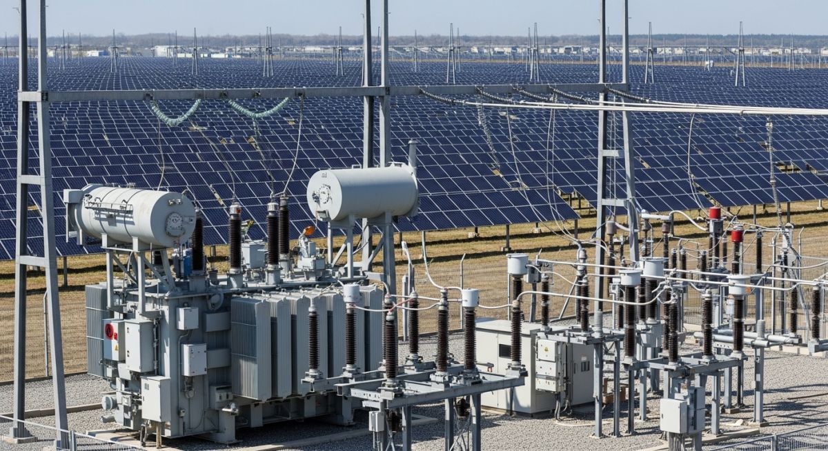
Grid Integration of Solar Power Plants: Technical Design Essentials
In my two decades of experience managing large-scale energy infrastructure, I have observed that the transition from traditional synchronous generation to inverter-based resources (IBR) represents the most significant shift in modern electrical engineering. The grid integration of solar power plants is not merely about installing panels; it is about mastering the complex interplay between intermittent DC generation and the rigid requirements of an AC transmission system.
Engineers must account for the lack of inherent inertia in solar arrays, which necessitates advanced control strategies to maintain system stability during transient events. This guide explores the technical rigor required to meet modern grid codes, focusing on reactive power compensation, fault ride-through capabilities, and the sophisticated power electronics that define modern solar utility projects.
Key Takeaways for Project Success:
- Understanding the impact of low-inertia systems on frequency regulation.
- Implementing active power curtailment and ramp-rate control for grid stability.
- Ensuring compliance with IEEE 1547-2018 for interconnection requirements.
- Optimizing reactive power management using smart inverter technology.
Grid Integration of Solar Power Plants: Advanced Control Systems
Grid Integration of Solar Power Plants: The technical framework governing the conversion, conditioning, and injection of solar-derived power into the grid, requiring precise control of voltage magnitude and phase angle through advanced power electronics.
The primary challenge in integrating solar power lies in the stochastic nature of solar irradiance and the absence of rotating mass. Unlike thermal plants, solar inverters are decoupled from the grid by DC-link capacitors, meaning they do not provide natural inertial response. To compensate, we utilize “Grid-Forming” and “Grid-Following” inverter control topologies. The fundamental equation for active power control in these systems is P = (V_inv * V_grid / X) * sin(delta), where delta represents the phase angle difference between the inverter output and the grid voltage.
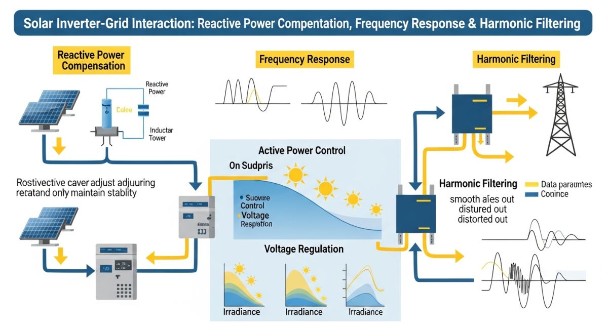
Voltage control is achieved through reactive power (Q) injection or absorption. Modern inverters must operate within a defined P-Q capability curve, often mandated by grid operators to provide voltage support even when the plant is not producing active power. This is governed by the IEC 61727 standard, which dictates the allowable voltage operating ranges and disconnection times for utility-scale systems.
Engineering Warning: Fault Ride-Through (FRT)
Failure to implement robust Low-Voltage Ride-Through (LVRT) profiles can lead to mass disconnection of solar assets during minor grid disturbances. This creates a cascading failure scenario. Ensure your inverter settings comply with NERC PRC-024 requirements for voltage and frequency ride-through, specifically testing the plant’s ability to remain connected during a 0.15 per-unit voltage dip for at least 0.5 seconds.
Frequency control is increasingly managed through synthetic inertia. By utilizing the energy stored in the DC-link capacitors or by curtailing the plant’s output slightly below the maximum power point (MPPT), the inverter can provide a rapid power boost during frequency drops. This requires a high-speed communication loop between the plant controller and the inverter fleet, typically operating at sub-100 millisecond latency.
Grid Integration Performance Metrics: A comparative analysis of the operational benefits and technical constraints inherent in modern solar-to-grid interconnection strategies.
Operational Advantages
- Dynamic reactive power support improves local voltage profiles.
- Reduced transmission losses through distributed generation placement.
- Rapid response times of power electronics compared to mechanical governors.
- Enhanced grid flexibility via smart inverter software updates.
Technical Disadvantages
- Lack of physical inertia increases rate-of-change-of-frequency (RoCoF) risks.
- Harmonic distortion requires sophisticated active filtering solutions.
- Complexity in protection coordination due to limited fault current contribution.
- High sensitivity to grid-side voltage imbalances and phase shifts.
Utility-Scale Integration Scenarios: Practical deployment environments where advanced grid-following and grid-forming control strategies are essential for system reliability.
Remote Microgrid Stabilization
In remote mining or islanded operations, solar plants must act as the primary voltage source. This requires grid-forming inverters that establish the reference frequency and voltage, effectively replacing the role of traditional diesel generators in maintaining system stability.
Urban Distribution Network Support
High penetration of rooftop solar in urban areas often causes voltage rise issues at the end of distribution feeders. Smart inverters are deployed here to perform Volt-VAR optimization, automatically absorbing reactive power to keep feeder voltages within the ANSI C84.1 standard limits.
Industrial Peak Shaving Infrastructure
Large manufacturing facilities utilize solar arrays coupled with battery energy storage systems (BESS) to manage peak demand charges. The integration controller manages the transition between grid-tied and islanded modes, ensuring that the facility’s sensitive equipment never experiences a power quality event during the switch.
Successful grid integration of solar power plants requires strict adherence to operational parameters that define the interaction between the inverter-based resource and the utility network. These parameters are not merely suggestions but are mandated by regional transmission organizations to ensure that the intermittent nature of solar energy does not compromise the overall reliability of the electrical grid.
The following table outlines the critical performance metrics that engineers must monitor during the commissioning and operational phases of a utility-scale solar project. These values are derived from IEEE 1547 and NERC reliability standards, which dictate how solar plants must respond to transient grid disturbances and steady-state voltage fluctuations.
| Parameter | Standard Range | Primary Objective |
|---|---|---|
| Voltage Ride-Through | 0.85 to 1.10 per unit | Prevent nuisance tripping during faults |
| Frequency Response | 59.5 to 60.5 Hertz | Maintain system stability during load shifts |
| Power Factor Control | 0.95 lead to 0.95 lag | Manage local reactive power demand |
| Harmonic Distortion | Less than 5 percent THD | Ensure power quality for end users |
Engineers should note that these ranges are subject to local grid code modifications. Always verify the specific interconnection agreement for your project site, as utility-specific requirements often impose stricter limits than the baseline national standards.
The complexity of modern solar integration necessitates a clear understanding of the various technical entities and their governing standards. This matrix maps the physical components of a solar plant to their respective regulatory and operational frameworks, providing a roadmap for compliance and system design.
By aligning hardware specifications with the appropriate IEC and ASME standards, project teams can mitigate the risks associated with grid instability and equipment failure. This mapping is essential for procurement, design review, and long-term asset management.
| Entity | Acronym | Standard Reference |
|---|---|---|
| Inverter-Based Resource | IBR | IEEE 2800 |
| Point of Interconnection | POI | IEEE 1547 |
| Static Synchronous Compensator | STATCOM | IEC 62927 |
| Supervisory Control and Data Acquisition | SCADA | IEC 61850 |
Utilizing this matrix during the early stages of project development ensures that all stakeholders, from the EPC contractor to the utility operator, are aligned on the technical requirements. This proactive approach significantly reduces the likelihood of costly retrofits or grid connection delays.
Before energizing any utility-scale solar facility, a comprehensive site verification process is mandatory. This checklist serves as a final gatekeeper, ensuring that all electrical infrastructure, control systems, and safety protocols meet the stringent requirements of the grid operator. In my experience, skipping these steps often leads to catastrophic failure during the initial synchronization phase.
-
Protection Relay Settings: Verify that all relay settings match the approved coordination study and NERC PRC standards. -
Communication Latency: Test SCADA response times to ensure control signals reach the inverters within the required millisecond window. -
Grounding Integrity: Perform soil resistivity and ground grid impedance testing to ensure compliance with IEEE 80. -
Harmonic Analysis: Confirm that the total harmonic distortion at the POI remains within the limits specified by the utility interconnection agreement. -
Reactive Power Capability: Validate the plant’s ability to provide dynamic voltage support across the full range of active power output.
Each item on this list must be documented with signed test reports and calibration certificates. If any parameter falls outside the acceptable threshold, the system must be re-tuned before proceeding to the final grid synchronization. Remember, the grid operator prioritizes stability above all else; any deviation from these standards will result in immediate rejection of the interconnection request.
The Challenge: Voltage Instability at the Point of Interconnection
A 100MW solar plant experienced frequent tripping during low-load conditions due to excessive voltage rise at the POI.
- Inadequate reactive power compensation during low solar irradiance.
- High impedance in the local distribution feeder causing voltage spikes.
- Lack of coordinated voltage control between the plant and the utility substation.
- Inverter settings were not optimized for the specific grid topology.
The Outcome: Successful Grid Stabilization and Compliance
By implementing a centralized plant controller and upgrading the reactive power compensation equipment, the plant achieved full compliance.
- Reduced voltage fluctuations by 40 percent during peak solar production.
- Eliminated nuisance tripping events, increasing annual energy production by 3 percent.
- Achieved full compliance with local grid codes regarding reactive power support.
- Improved communication reliability between the plant and the utility control center.
My recommendation for similar projects is to conduct a thorough power system study during the design phase, specifically focusing on the interaction between the plant’s inverters and the grid’s existing impedance. Do not rely solely on default inverter settings; custom tuning is almost always required to ensure stable operation in weak grid environments.
How does solar integration affect grid frequency?
- Inverters must be programmed to adjust active power output in response to frequency changes.
- This mimics the governor response of traditional turbines to stabilize the grid.
- Compliance with IEEE 2800 is critical for ensuring these features function correctly.
What is the role of reactive power in grid stability?
- Solar inverters can operate in four-quadrant mode to provide or absorb reactive power.
- This dynamic support is vital for voltage regulation at the point of interconnection.
- Engineers must ensure the inverter’s reactive power capability curve covers the full range of expected grid conditions.
Why is harmonic distortion a concern for solar plants?
- Filters are integrated into the inverter design to mitigate high-frequency noise.
- Compliance with IEEE 519 is the industry standard for harmonic limits.
- Regular monitoring at the POI is necessary to ensure ongoing compliance as the grid environment changes.
What are low-voltage ride-through requirements?
- Inverters must be capable of injecting reactive current during the fault to support voltage recovery.
- The specific duration and depth of the ride-through are defined by regional grid codes.
- Failure to meet these requirements can lead to the plant being disconnected from the grid during minor faults.
How does SCADA improve grid integration?
- Enables remote curtailment during periods of grid congestion.
- Provides data for post-event analysis of grid disturbances.
- Ensures that the plant adheres to the dispatch instructions provided by the utility.
What is the importance of grid codes?
- They define the minimum performance standards for voltage and frequency control.
- They establish the communication and data exchange protocols between the plant and the utility.
- Adherence to these codes is a legal requirement for any utility-scale energy project.
Complete Course on
Piping Engineering
Check Now
Key Features
- 125+ Hours Content
- 500+ Recorded Lectures
- 20+ Years Exp.
- Lifetime Access
Coverage
- Codes & Standards
- Layouts & Design
- Material Eng.
- Stress Analysis
