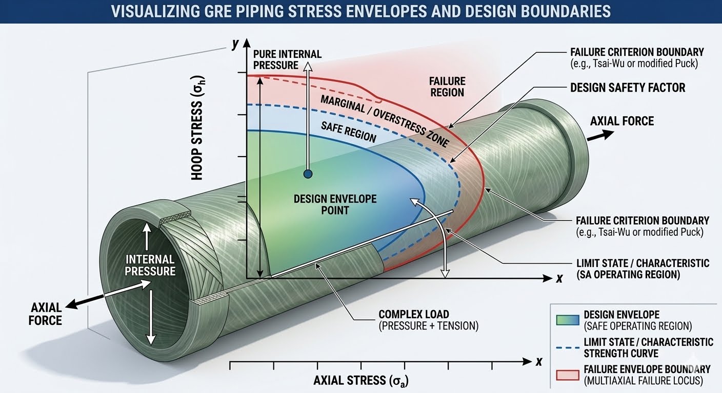
Understanding the GRE Design Envelope for Safe Piping Operations
In my 20 years of commissioning composite piping systems in offshore environments, I have seen many engineers treat Glass Reinforced Epoxy (GRE) like carbon steel. This is a recipe for catastrophic failure. Unlike isotropic steel, GRE is highly anisotropic, meaning its mechanical properties vary significantly depending on the direction of the glass fibers. To design and operate these systems safely, we must rely on the GRE design envelope.
During my early days on a North Sea platform project, we faced recurring joint leaks because the stress analysis team ignored the combined effects of thermal expansion and internal pressure. They analyzed these forces independently. When we plotted the actual operating coordinates, we discovered they fell well outside the qualified design envelope, even though the pressure was below the nominal rating. This taught me that mastering the interaction between axial and hoop stresses is the only way to ensure long-term integrity.
- Composite piping systems require simultaneous evaluation of axial and hoop stresses rather than independent limits.
- The design envelope is a scaled-down version of the failure envelope, incorporating long-term regression factors and safety margins.
- Thermal expansion in GRE generates lower forces than steel, but the resulting axial displacement can easily destabilize unguided runs.
Complete Course on
Piping Engineering
Check Now
Key Features
- 125+ Hours Content
- 500+ Recorded Lectures
- 20+ Years Exp.
- Lifetime Access
Coverage
- Codes & Standards
- Layouts & Design
- Material Eng.
- Stress Analysis
Mastering the GRE Design Envelope Parameters
To understand the design envelope, we must first look at the failure envelope. The failure envelope is established through short-term and long-term destructive testing, such as ASTM D2992. Manufacturers subject pipe samples to various ratios of hoop-to-axial stress (typically 2:1, 1:1, and 0:1) until weepage or structural collapse occurs. This maps out the ultimate limit state of the material.
The design envelope is then constructed by applying a series of reduction factors to this failure boundary. These factors account for chemical degradation, temperature effects, cyclic loading, and a service design factor (typically 0.5 for standard hydrocarbon service). The resulting envelope is a smaller, safe operating zone.
Never assume that a pipe rated for 16 bar can handle 16 bar under all piping configurations. If your system experiences high axial tension due to structural settlement or thermal contraction, the allowable internal pressure drops significantly. Always verify the combined stress state.
Let us look at the mathematical relationship governing these limits. The hoop stress is calculated using the classic thin-walled formula:
Hoop Stress = (Internal Pressure * Mean Diameter) / (2 * Minimum Reinforced Wall Thickness)
Simultaneously, the axial stress is a combination of pressure thrust, thermal expansion, and external bending moments:
Axial Stress = (Internal Pressure * Mean Diameter) / (4 * Minimum Reinforced Wall Thickness) + (Bending Moment / Section Modulus) + (Axial Force / Cross-Sectional Area)
In GRE systems, the winding angle of the glass fibers (usually around 55 degrees) is optimized to handle twice the hoop stress relative to axial stress. This matches the natural 2:1 stress ratio of a closed-end cylinder under pressure. However, when external loads like soil settlement or wind loads alter this ratio, the operating point shifts toward the envelope boundaries, risking premature weepage.
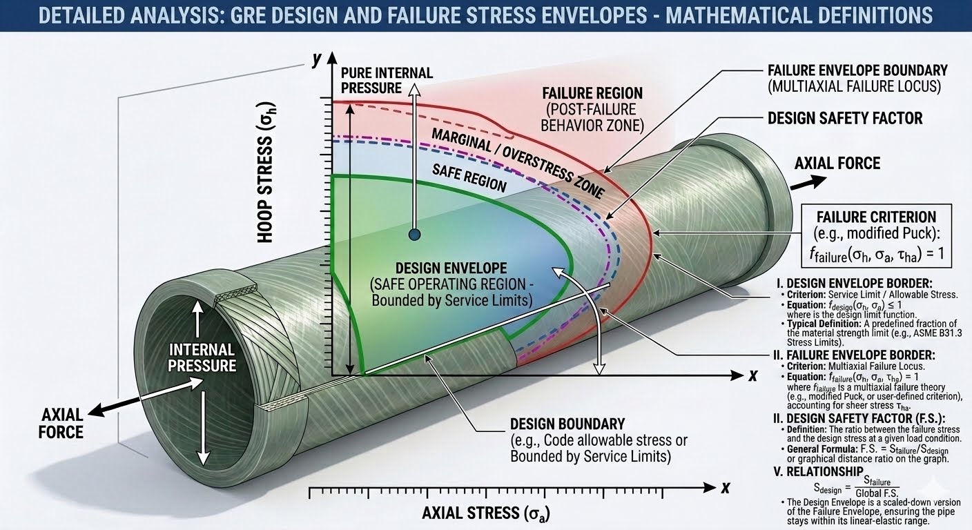
For detailed compliance, engineers must refer to the ISO 14692 standard, which outlines the exact methodology for calculating these stress coordinates and comparing them against manufacturer-supplied envelope curves.
Analyzing GRE Design Envelope Stress Limits
The table below outlines typical stress limits for standard GRE piping systems across different nominal sizes and operating temperatures. These values are representative and must be verified against specific manufacturer data sheets compliant with ISO 14692.
| Nominal Pipe Size (NPS) | Design Temp (°C) | Max Hoop Stress (MPa) | Max Axial Tension (MPa) | Max Axial Compression (MPa) |
|---|---|---|---|---|
| 2″ to 6″ | 65 | 68.5 | 34.2 | 25.0 |
| 2″ to 6″ | 93 | 52.0 | 26.0 | 18.5 |
| 8″ to 16″ | 65 | 62.0 | 31.0 | 22.0 |
| 8″ to 16″ | 93 | 45.5 | 22.7 | 15.0 |
To ensure seamless communication between stress analysts and field engineers, this matrix maps key technical entities, physical parameters, and their governing standards.
| Entity / Acronym | Technical Definition | Physical Parameter | Reference Standard |
|---|---|---|---|
| LTHS | Long-Term Hydrostatic Strength extrapolated to 50 years | Hydrostatic Pressure (MPa) | ASTM D2992 |
| HDB | Hydrostatic Design Basis for composite materials | Hoop Stress (MPa) | ASTM D2992 |
| Part 6 (ISO 14692) | System design and stress analysis requirements | Combined Stress State | ISO 14692-3 |
Site Verification Checklist for GRE Piping
Before introducing pressure into any newly installed GRE system, I always run through a strict field verification protocol. This prevents unexpected displacements that could push the system past its design envelope.
-
Support Alignment: Verify all guide supports allow axial movement without binding, preventing localized compressive stress spikes. -
Anchor Rigidity: Confirm structural anchors are fully grouted and bolted to absorb the calculated pressure thrust forces. -
Expansion Loop Clearance: Ensure expansion loops have at least 150mm of clear space to flex without hitting structural steel. -
Hydrotest Pressure Limits: Limit the field hydrotest pressure to 1.5 times the design pressure, ensuring it does not cross the short-term failure envelope boundary.
Field Case Study: Real-World Application
During a produced water system upgrade at an onshore terminal, a 12-inch GRE header experienced repeated joint failures at a 45-degree elbow. The operating pressure was only 8 bar, well below the 16 bar nominal rating of the pipe. The engineering team was baffled. When I reviewed the stress model, I noticed they had modeled the system with rigid steel-like supports. The thermal expansion of the GRE pipe at 60°C was restricted, generating massive compressive axial forces that pushed the combined stress state outside the design envelope.
We redesigned the support scheme by replacing three rigid guides with loose-fit guide clamps and adding a structural anchor before the elbow. This allowed the pipe to expand safely into a designated expansion loop, reducing the axial compressive stress from 32 MPa to 8 MPa. The combined stress coordinate moved back into the safe zone of the GRE design envelope, and the system has operated without a single leak for over five years.
My recommendation for any composite piping project is to perform a comprehensive stress analysis using specialized software like CAESAR II, ensuring that the actual manufacturer’s envelope is imported directly into the model rather than relying on generic default values.
Frequently Asked Engineering Questions
What is the primary difference between a design envelope and a failure envelope?
How does temperature affect the GRE design envelope?
Why is the winding angle of GRE fibers critical to the envelope shape?
Can water hammer push a system outside its design envelope?
What safety factor is typically applied to the failure envelope?
How do external bending moments impact the design envelope?

📚 Recommended Resources: GRE Design Envelope
Read these Guides
- 📄 What are Industrial Agitators? Selection, Types & Design Explained from Field Experience
- 📄 What are Hub & Clamp Connectors? | Design, Benefits, and Applications
- 📄 Basis of Design: How to Write a BOD for Engineering Projects in 2026
- 📄 Determination of Design Pressure and Design Temperature: Engineering Guide 2026