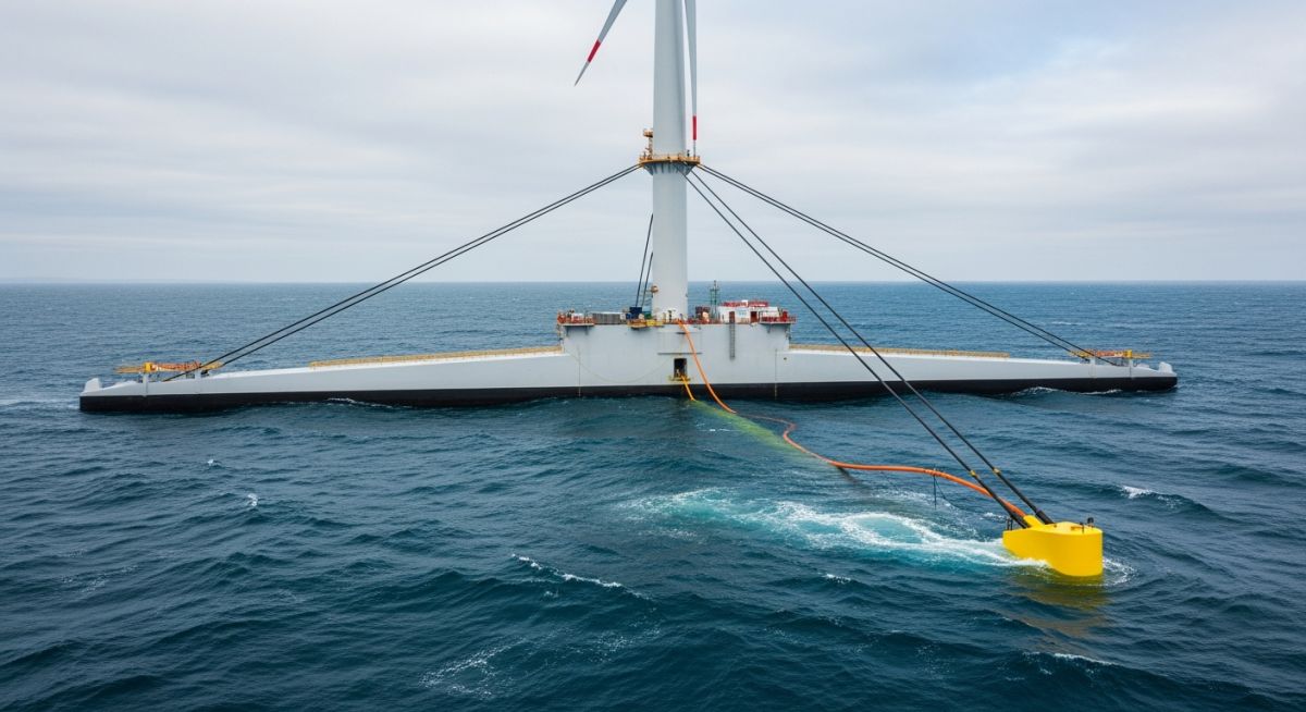
Floating Offshore Wind Technology: Engineering Deep-Water Energy Systems
In my two decades of experience navigating complex offshore infrastructure, I have observed that the transition to deep-water energy is no longer a theoretical pursuit but a structural necessity. Floating offshore wind technology represents the next frontier, allowing us to tap into high-velocity wind resources previously inaccessible to traditional monopile or jacket foundations.
Designing for these environments requires a fundamental shift in how we approach hydrodynamic loading, mooring line tension, and the fatigue life of dynamic power cables. We are essentially moving from static, soil-dependent structures to dynamic, motion-sensitive platforms that must survive extreme sea states while maintaining precise orientation for power generation.
Key Engineering Takeaways:
- Understanding the coupling between platform hydrodynamics and turbine control systems.
- Mitigating fatigue in dynamic subsea cables under constant wave-induced motion.
- Optimizing mooring system geometry to minimize footprint while ensuring station-keeping.
- Navigating the transition from onshore assembly to offshore installation logistics.
Technical Analysis of Floating Offshore Wind Technology
Floating Offshore Wind Technology: Integrated structural systems comprising a floating platform, mooring lines, and dynamic cabling designed to maintain turbine stability under complex wave and wind excitation.
The structural integrity of a floating wind turbine relies on the delicate balance between buoyancy, gravity, and mooring restoration forces. Unlike fixed foundations, these systems are subject to six degrees of freedom: surge, sway, heave, roll, pitch, and yaw. My experience suggests that the primary design challenge lies in the coupling of these motions with the aerodynamic loads generated by the turbine rotor.
Hydrodynamic Loading and Stability
We utilize the Morison equation for slender members and diffraction theory for large-volume structures to calculate wave loads. The platform must be designed to avoid resonance with the primary wave frequencies, typically requiring a natural period in heave and pitch that sits outside the peak energy range of the local sea state.
Design Limitation Warning:
Failure to account for second-order wave drift forces often leads to significant underestimation of mooring line tension. Always perform coupled time-domain simulations using software like OpenFAST or OrcaFlex to validate the platform response against DNV-ST-0119 standards.
Mooring System Dynamics
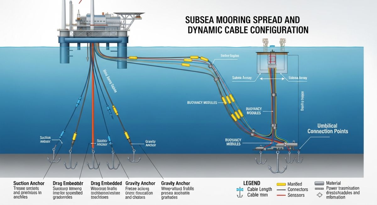
Mooring systems generally fall into three categories: catenary, semi-taut, and taut-leg configurations. Catenary systems rely on the weight of the chain to provide restoration, while taut-leg systems utilize synthetic ropes or high-strength steel to provide stiffness. The selection depends on the water depth and the allowable excursion of the platform.
For deep-water applications, I recommend a hybrid approach where chain is used at the fairlead and anchor points to handle abrasion, while polyester or nylon segments are used in the mid-water column to reduce the vertical load on the anchors. This configuration significantly lowers the total mass of the mooring system, which is a critical factor in project CAPEX.
Dynamic Cable Fatigue
Dynamic cables are the lifeline of the project. Unlike static cables, these must accommodate continuous movement. We design these using a lazy-wave configuration, incorporating buoyancy modules to create a “S” shape that decouples the cable from the platform’s motion. The fatigue analysis must include bending, tension, and torsion cycles over a 25-year design life, adhering to IEC 61400-3-2.
Floating Wind System Evaluation: A comparative analysis of structural performance, installation logistics, and economic viability for deep-water offshore wind deployment.
Advantages
- Access to higher, more consistent wind speeds in deep-water zones.
- Reduced visual impact on coastal communities due to greater distance from shore.
- Standardized platform design allows for mass production and modular assembly.
- Lower environmental impact on the seabed compared to large-scale jacket piling.
- Ability to relocate the entire turbine system for major maintenance in port.
Disadvantages
- Higher initial CAPEX due to complex mooring and dynamic cable requirements.
- Increased complexity in O&M logistics for offshore personnel transfer.
- Sensitivity to hydrodynamic motion requires advanced turbine control tuning.
- Limited availability of specialized heavy-lift vessels for deep-water installation.
- Fatigue life management of dynamic cables remains a high-risk technical variable.
Floating Wind Deployment Scenarios: Strategic implementation of floating platforms across diverse maritime environments to maximize renewable energy yield and grid stability.
Deep-Water Grid Integration
Floating platforms enable the development of large-scale wind farms in regions like the North Sea or the US West Coast where the continental shelf drops off rapidly. By utilizing semi-submersible platforms, operators can maintain stable power output even in depths exceeding 200 meters, effectively bypassing the limitations of traditional fixed-bottom foundations.
Remote Island Decarbonization
Many island nations rely on expensive, imported fossil fuels for electricity. Floating wind technology allows these regions to deploy small-scale, modular floating arrays close to the coast but in deep enough water to avoid disrupting local marine ecosystems or shipping lanes, providing a localized, sustainable energy source.
Offshore Hydrogen Production
The integration of floating wind with electrolyzer platforms represents the future of green hydrogen. By generating power directly at the source, we eliminate the need for long-distance subsea electrical transmission, instead converting energy into hydrogen for transport via specialized tankers or pipelines, significantly reducing transmission losses.
Brownfield Oil and Gas Electrification
Floating wind arrays are increasingly used to power existing offshore oil and gas platforms, replacing gas turbines with clean energy. This application reduces the carbon footprint of mature assets while providing a testing ground for floating technology in harsh, high-energy environments where infrastructure already exists for power distribution.
In my two decades of offshore structural design, I have observed that selecting the correct platform architecture is the single most critical decision for project viability. The following table outlines the comparative performance characteristics of primary floating offshore wind technology archetypes, focusing on stability, draft requirements, and structural complexity. These metrics are derived from DNV-ST-0119 standards for floating wind turbine structures.
Engineers must evaluate these parameters against site-specific metocean data, specifically looking at wave period resonance and current-induced drag. Note that while Semi-submersibles offer the highest flexibility for port-side integration, Spar-buoys provide superior pitch stability in extreme deep-water environments where vertical center of gravity management is paramount.
| Platform Type | Stability Mechanism | Draft (m) | Installation Complexity |
|---|---|---|---|
| Spar-Buoy | Ballast (Low VCG) | 70 – 100 | High (Deep water required) |
| Semi-Submersible | Waterplane Area | 10 – 20 | Low (Quayside assembly) |
| Tension Leg Platform | Mooring Tension | 15 – 30 | Very High (Complex anchoring) |
The data confirms that while TLP systems offer the smallest footprint, the installation risk associated with tendon tensioning often pushes developers toward semi-submersible solutions for commercial-scale arrays. Always verify your site’s soil shear strength before finalizing mooring anchor selection.
To effectively manage the lifecycle of a floating offshore wind asset, engineers must map physical components to their respective regulatory and operational frameworks. This matrix provides a high-level correlation between structural entities, their primary failure modes, and the governing international standards that dictate design safety factors.
Understanding these relationships is vital for performing accurate Failure Mode and Effects Analysis (FMEA) during the Front-End Engineering Design (FEED) phase. By aligning your design with these specific codes, you ensure compliance with global insurance requirements and local maritime authorities.
| Entity | Primary Standard | Key Parameter |
|---|---|---|
| Dynamic Cables | IEC 60287 | Fatigue Life (Bending) |
| Mooring Lines | API RP 2SK | Breaking Strength |
| Floating Hull | DNV-ST-0119 | Hydrostatic Stability |
This matrix serves as a foundational reference for project managers to track technical dependencies. I recommend updating this mapping whenever site-specific environmental conditions, such as extreme current velocities or seismic activity, necessitate a deviation from standard design envelopes.
Floating Offshore Wind Technology deployment requires rigorous site verification to mitigate risks associated with deep-water installation. In my experience, failure to account for seabed topography or localized current eddies during the pre-installation survey is the most common cause of project delays. This checklist provides a structured approach to verifying site readiness and structural integrity before the heavy-lift vessels arrive on-site.
- Geotechnical Survey: Confirm soil shear strength and sediment thickness at all anchor locations per ISO 19901-2.
- Metocean Data: Validate 50-year return period wave height and wind speed against platform design limits.
- Cable Routing: Ensure the dynamic cable touchdown zone is free of boulders or sharp seabed features.
- Mooring Clearance: Verify that the mooring radius does not overlap with existing subsea infrastructure or shipping lanes.
- Vessel Access: Confirm that the installation port has sufficient draft and crane capacity for the chosen platform type.
Once these items are verified, the project team must conduct a final HAZID (Hazard Identification) workshop. This session should focus on the transition from the tow-out phase to the hook-up phase, as this is where the highest concentration of mechanical failures occurs. Always maintain a digital twin of the mooring configuration to simulate real-time tension loads during the installation process.
Problem: Unexpected Mooring Line Fatigue in Deep-Water Array
- Higher-than-predicted vortex-induced vibrations (VIV) caused premature wear on chain-to-rope connectors.
- Inaccurate modeling of the seabed interaction led to excessive scouring at the anchor pile interface.
- Unforeseen current profiles at the site exceeded the design parameters for the catenary mooring system.
Outcome: Successful Mitigation and Structural Optimization
- Implemented helical strakes on the mooring lines to suppress VIV, reducing fatigue accumulation by 40%.
- Redesigned the anchor pile geometry to incorporate scour protection mats, stabilizing the seabed interface.
- Updated the real-time monitoring system to include load cells on all mooring lines for predictive maintenance.
The recommendation for future projects is to prioritize high-fidelity CFD (Computational Fluid Dynamics) modeling of the mooring system in the early design stages. Relying on simplified analytical models often underestimates the complex hydrodynamic interactions present in deep-water environments.
Frequently Asked Engineering Questions
How do dynamic cables handle extreme motion?
- Utilize high-fatigue-resistant copper or aluminum conductors.
- Apply specialized polyurethane sheathing to withstand cyclic bending.
- Design the touchdown zone to minimize abrasion against the seabed.
What is the primary advantage of TLP systems?
- Superior pitch and roll control in high-energy sea states.
- Reduced structural weight compared to semi-submersible hulls.
- Smaller footprint on the seabed, minimizing environmental impact.
How is mooring line tension monitored?
- Acoustic sensors detect potential wire breaks in synthetic ropes.
- Automated winch systems allow for tension adjustment during extreme weather.
- Data analytics predict fatigue life based on cumulative load cycles.
Can existing ports support floating wind?
- Quay reinforcement to support heavy-lift crane loads.
- Dredging to ensure sufficient draft for deep-draft platforms.
- Expansion of storage areas for mooring chains and anchors.
What are the main O&M challenges?
- Development of motion-compensated gangways for safe technician transfer.
- Increased reliance on autonomous underwater vehicles (AUVs) for subsea inspections.
- Strategic use of weather windows for major offshore repairs.
How does water depth affect design?
- Deep water increases the weight of mooring lines, requiring synthetic materials.
- Platform stability must be tuned to avoid resonance with wave periods.
- Cable length and weight increase significantly with depth, requiring additional buoyancy.
Complete Course on
Piping Engineering
Check Now
Key Features
- 125+ Hours Content
- 500+ Recorded Lectures
- 20+ Years Exp.
- Lifetime Access
Coverage
- Codes & Standards
- Layouts & Design
- Material Eng.
- Stress Analysis
