How to Perform Flanged Elbow Stress Analysis in Piping Systems
In my 20-plus years of piping engineering, I have seen many young engineers fall into the trap of treating every elbow in a CAESAR II model as a standard, unconstrained bend. Early in my career, I made a similar mistake on a high-pressure hydrocarbon line. The software model showed plenty of flexibility, but the real-world system suffered from excessive nozzle loads at the pump. The culprit? A heavy Class 600 flange welded directly to a 12-inch long radius elbow.
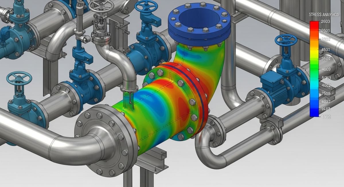
When you weld a rigid steel flange to an elbow, you fundamentally alter its structural behavior. The flange acts as a stiffening ring, preventing the elbow from ovalizing under bending moments. This structural reality can make or break your piping design, especially when dealing with high-temperature lines or sensitive equipment connections.
- Flanges restrict the natural ovalization of elbows, significantly reducing piping system flexibility.
- Ignoring the stiffening effect of flanges leads to underestimating equipment nozzle loads and support forces.
- ASME B31.3 Appendix D and ASME B31J provide specific multipliers to adjust flexibility and stress intensification factors (SIF).
- Modern stress analysis software requires manual input to correctly apply these flanged boundary conditions.
- Field verification is necessary to ensure the physical piping matches the modeled flange configurations.
Why Flanged Elbow Stress Analysis Matters for Flexibility
To understand why this happens, we must look at the physics of a bending elbow. When a straight pipe is subjected to a bending moment, its cross-section remains circular. However, when an elbow is subjected to an in-plane bending moment, its cross-section flattens into an ellipse. This phenomenon is known as ovalization or the Karman effect.
Ovalization is highly beneficial for piping flexibility. It allows the elbow to bend more easily, acting like a structural hinge that absorbs thermal expansion. The flexibility characteristic, represented by the variable “h”, determines how much the elbow can ovalize. For a standard, unconstrained elbow, this is calculated using the following formula:
Where:
t = Nominal wall thickness of the matching pipe
R = Bend radius of the elbow
r_m = Mean radius of the matching pipe
When you weld a heavy, rigid flange to one or both ends of the elbow, you introduce a boundary condition that completely prevents ovalization at that interface. The flange acts as a rigid ring, forcing the elbow end to remain perfectly circular. This restriction propagates along the arc of the bend, making the entire elbow stiffer.
In my consulting practice, I have investigated three major pump nozzle failures where the stress analyst forgot to flag the pump inlet elbow as “flanged” in CAESAR II. The software assumed a highly flexible elbow, showing nozzle loads well within API 610 limits. In reality, the rigid flanged elbow transferred massive thermal expansion forces directly to the pump casing, causing shaft misalignment and eventual casing cracking.
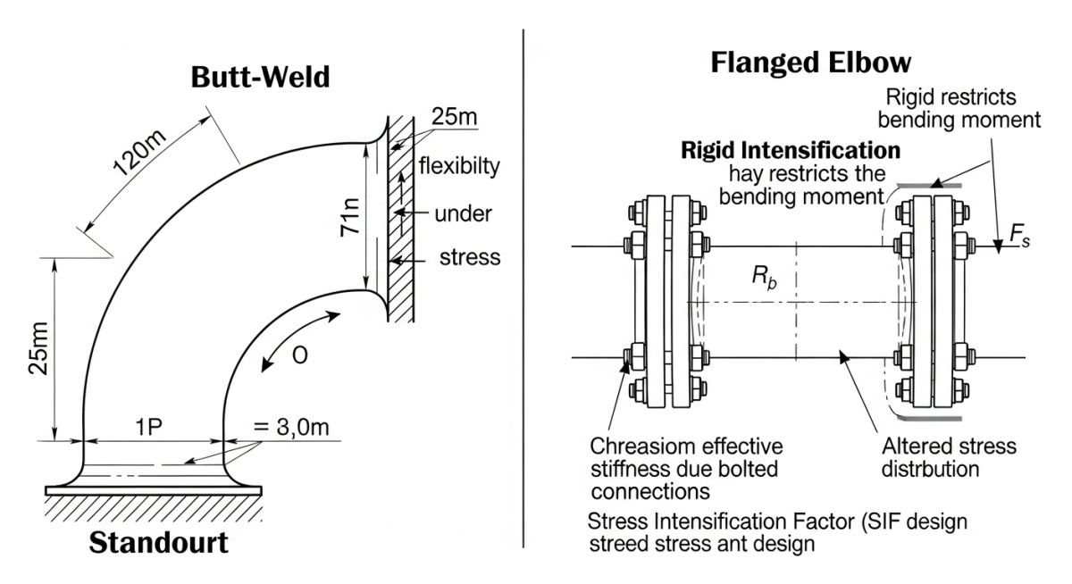
To account for this stiffening, piping codes like ASME B31.3 Process Piping Code and ASME B31J introduce correction factors. These factors modify both the flexibility factor (k) and the stress intensification factor (i) based on whether one or both ends of the elbow are flanged.
For example, under ASME B31.3 Appendix D, the flexibility factor (k) for an un-flanged elbow is:
If one end is flanged, the flexibility factor is reduced by a multiplier:
If both ends are flanged, the reduction is even more severe:
This reduction in the flexibility factor means the elbow is significantly stiffer, which directly increases the forces and moments transmitted to adjacent piping and equipment.
Step-by-Step Flanged Elbow Stress Analysis in CAESAR II
When modeling in CAESAR II, the software does not automatically know if an elbow has flanges welded to it. You must explicitly define this in the bend input screen. Let us look at how these inputs affect the calculated flexibility and SIF values for a standard 8-inch NPS, Schedule 40, Long Radius Elbow.
| Elbow Configuration | Flexibility Characteristic (h) | Flexibility Factor (k) | In-Plane SIF (i_i) | Out-of-Plane SIF (i_o) | Stiffness Increase (%) |
|---|---|---|---|---|---|
| Un-flanged (Plain Bend) | 0.273 | 6.04 | 2.14 | 1.78 | Baseline (0%) |
| One End Flanged | 0.273 | 3.45 | 1.53 | 1.27 | 75% stiffer |
| Both Ends Flanged | 0.273 | 2.01 | 1.13 | 0.94 | 200% stiffer |
As shown in the table, adding flanges to both ends of the elbow reduces the flexibility factor from 6.04 to 2.01. This represents a massive 200% increase in localized stiffness. While the SIF values actually decrease (because the flange prevents the high-stress ovalization at the crotch), the loss of overall system flexibility almost always leads to higher reaction forces at the anchors and equipment nozzles.
To ensure complete compliance with international standards, use this technical mapping matrix to align your physical piping components with the correct stress analysis treatment.
| Piping Component | Code Reference | Physical Impact | Stress Analysis Treatment |
|---|---|---|---|
| Long Radius Elbow | ASME B31.3 | Standard ovalization under bending moments. | Model as standard bend element with default SIF. |
| Welded Flange (One End) | ASME B31J | Restricts ovalization on one side of the bend. | Apply “One End Flanged” multiplier in CAESAR II. |
| Welded Flange (Both Ends) | ASME B31J | Restricts ovalization on both sides of the bend. | Apply “Both Ends Flanged” multiplier in CAESAR II. |
| Flange Spool (Near Elbow) | ASME B31.3 Section 319 | Minor stiffening if within 2 pipe diameters. | Model flange element explicitly; do not flag elbow as flanged. |
How to Verify Flanged Elbow Models on Site
In my experience, a major source of piping failures is the disconnect between the stress analyst’s computer model and the actual physical installation on site. Use this checklist during your next site walkdown to ensure your flanged elbow stress analysis matches reality.
-
Verify Flange Proximity: Ensure that any flange modeled as “welded to the elbow” is physically welded directly to the elbow tangent line. If there is a straight pipe spool longer than two pipe diameters between the elbow and the flange, the elbow must be modeled as un-flanged.
-
Check Flange Rating and Class: Confirm that the physical flange rating (e.g., Class 150, 300, 600) matches the design specification. Higher class flanges are thicker and heavier, which increases the localized stiffening effect.
-
Inspect Support Locations: Verify that no rigid pipe supports or guides are welded directly to the flanged elbow assembly unless explicitly accounted for in the stress model.
-
Validate Bolt-Up Alignment: Ensure that the flange faces are perfectly aligned before bolt-up. Excessive cold-pull or misalignment during installation can introduce massive unmodeled stresses into the elbow.
-
Confirm Wall Thickness: Use ultrasonic testing (UT) if necessary to verify that the elbow wall thickness matches the nominal schedule specified in the stress model, as thinner walls are more sensitive to flange stiffening.
Field Case Study: Real-World Application
A high-temperature steam line operating at 350 degrees Celsius in a chemical plant was experiencing recurring steam leaks at a turbine inlet flange. The original stress analysis model treated the 90-degree inlet elbow as a standard, un-flanged bend. The model showed acceptable thermal expansion stresses and nozzle loads. However, the physical installation had heavy Class 300 flanges welded directly to both ends of the inlet elbow. Because the model did not account for the stiffening effect of these flanges, the calculated flexibility of the system was highly overestimated.
I was brought in to troubleshoot the system. We remodeled the inlet piping in CAESAR II, changing the elbow configuration to “Both Ends Flanged” and applying ASME B31J SIFs. The remodeled system showed a 45% reduction in elbow flexibility, which caused the calculated turbine nozzle loads to exceed the allowable limits by 180%. We resolved the issue by replacing the rigid flanged elbow with a welded elbow and relocating the flange 3 meters upstream, restoring system flexibility and stopping the leaks.
This case study highlights why you must never ignore the physical reality of your piping components. A simple checkbox in your stress analysis software can mean the difference between a safe, reliable plant and a catastrophic shutdown.
Frequently Asked Engineering Questions
How does a flange affect the stress intensification factor (SIF) of an elbow?
What is the difference between ASME B31.3 Appendix D and ASME B31J for flanged elbows?
Should I model a flange welded to a pipe spool near an elbow as “flanged”?
How do flanged elbows impact pump and turbine nozzle loads?
Can CAESAR II automatically detect flanged elbows from a 3D CAD model?
What are the risks of ignoring the flanged elbow stiffening effect?
===
Complete Course on
Piping Engineering
Check Now
Key Features
- 125+ Hours Content
- 500+ Recorded Lectures
- 20+ Years Exp.
- Lifetime Access
Coverage
- Codes & Standards
- Layouts & Design
- Material Eng.
- Stress Analysis