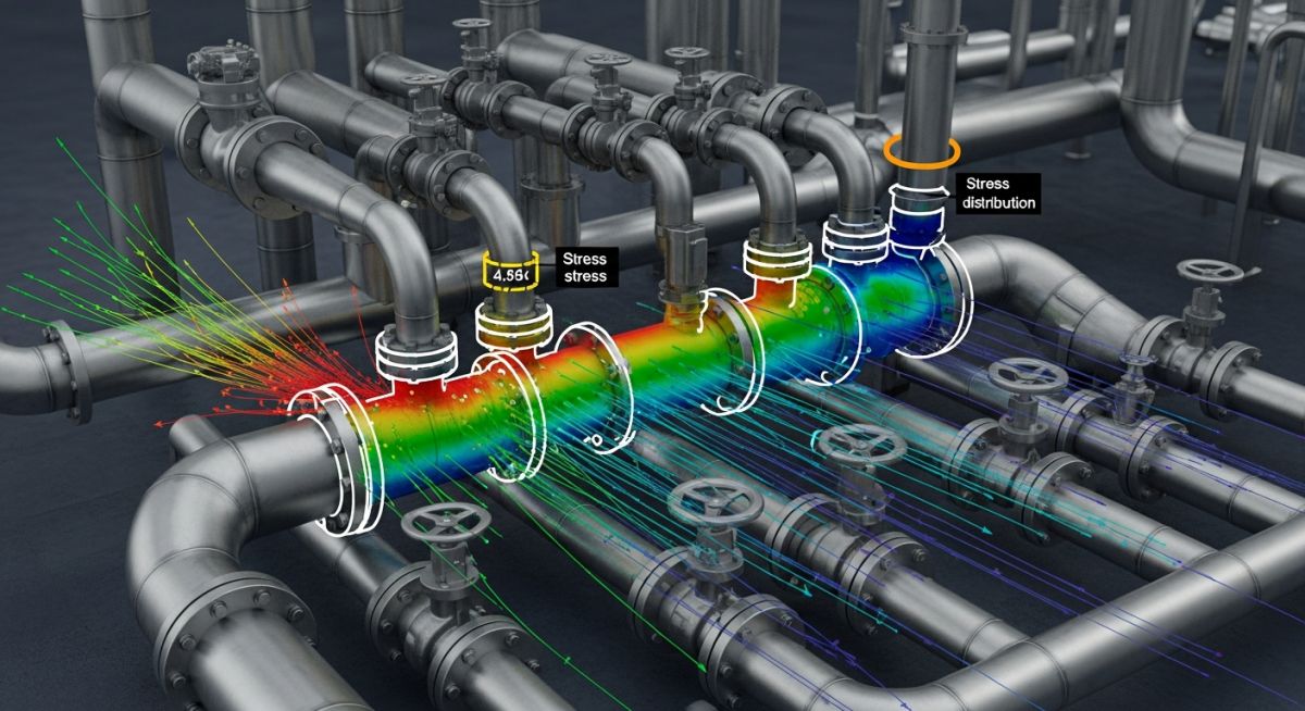
Flange Leakage Checking by Pressure Equivalent Method in Caesar II
In my two decades of experience as a piping stress engineer, I have seen countless projects delayed by field-reported flange leaks that could have been predicted during the design phase. While rigorous finite element analysis (FEA) is the gold standard for critical joints, the Pressure Equivalent Method in Caesar II provides a robust, efficient, and code-compliant screening tool for standard piping systems.
This method allows us to account for the combined effects of internal pressure, axial forces, and bending moments acting on a flange. By calculating an equivalent pressure, we can verify if the flange remains within its rated capacity under operating and sustained load cases. Mastering this workflow is essential for any engineer aiming to minimize site rework and ensure long-term plant safety.
Key Takeaways for Piping Engineers:
- Understand the conversion of external loads (F and M) into equivalent pressure (P_eq).
- Learn to interpret Caesar II output reports for flange leakage warnings.
- Ensure compliance with ASME B16.5 and B16.47 standards.
- Identify when to transition from simplified methods to full FEA analysis.
Mastering Flange Leakage Checking by Pressure Equivalent Method
Pressure Equivalent Method: A standardized engineering procedure that maps external piping forces and moments onto a flange face to determine if the total stress exceeds the allowable pressure-temperature rating defined by ASME standards.
When performing a stress analysis, the primary goal is to ensure that the flange assembly maintains a seal under all operating conditions. The Pressure Equivalent Method simplifies this by calculating an equivalent pressure (P_eq) using the formula: P_eq = P_internal + (16 * M) / (pi * G^3) + (4 * F) / (pi * G^2), where M is the bending moment, F is the axial force, and G is the effective gasket diameter.
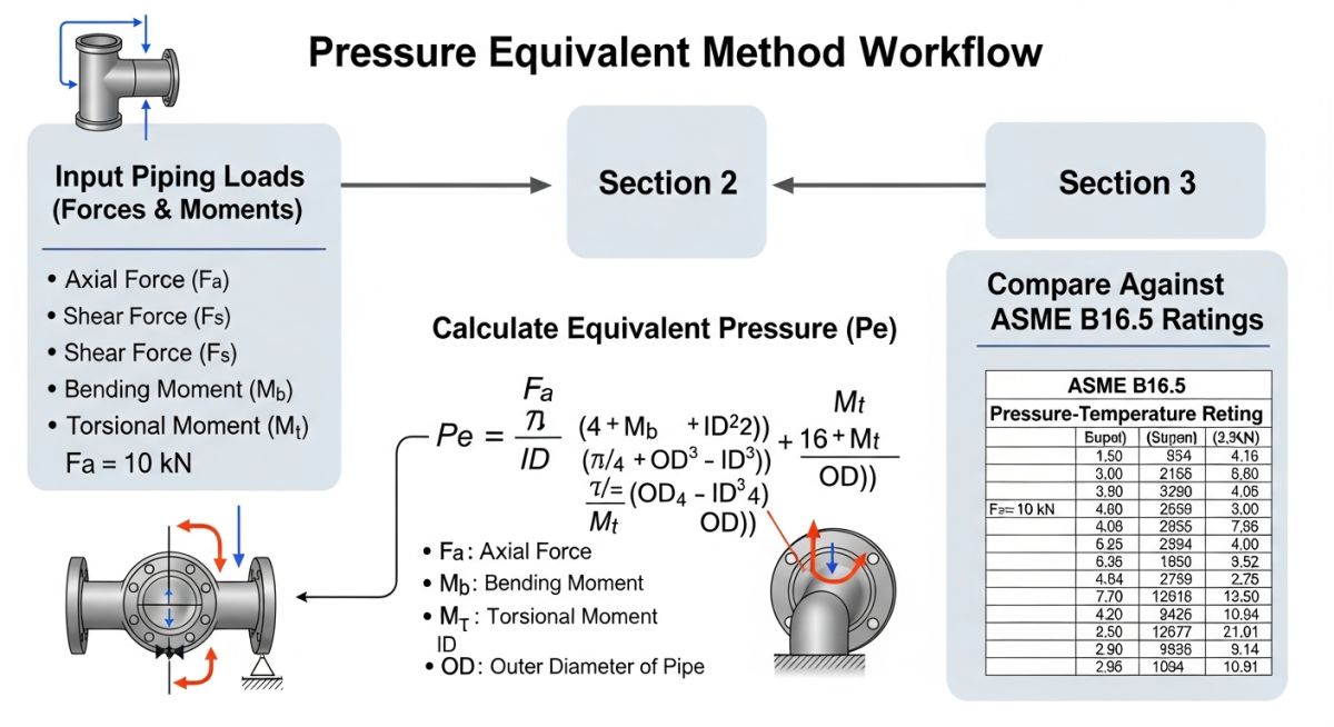
In Caesar II, this calculation is automated within the flange leakage check module. You must input the correct flange class, material, and gasket properties to ensure the software accurately references the ASME B16.5 tables. If the calculated P_eq exceeds the rated pressure for the given temperature, the software flags the joint as a potential leakage point.
Critical Engineering Limitation:
The Pressure Equivalent Method assumes the flange behaves as a rigid body. It does not account for bolt relaxation, thermal cycling effects on gasket seating, or non-linear flange rotation. For high-temperature services (above 400 degrees Celsius) or cyclic thermal loading, this method should be treated as a screening tool only, not a final validation.
To execute this in Caesar II, navigate to the ‘Flange Leakage’ tab in the input processor. You must define the flange type (e.g., Weld Neck, Slip-on) and the pressure rating. The software then extracts the forces and moments from the load cases (Operating, Sustained, and Occasional) to perform the check. Always verify that your load cases include the thermal expansion effects, as these are the most common contributors to flange leakage in high-pressure steam lines.
If a flange fails the check, you have three primary mitigation strategies: increasing the flange rating (e.g., from 150# to 300#), reducing the piping stiffness by adding expansion loops, or utilizing a higher-performance gasket material. In my experience, the most common error is failing to update the gasket diameter (G) in the Caesar II input, which leads to overly conservative or dangerously optimistic results.
Flange Leakage Analysis Trade-offs: A technical comparison between the efficiency of the Pressure Equivalent Method and the precision of advanced numerical modeling techniques.
Advantages
- Rapid screening of thousands of joints in complex piping networks.
- Direct integration with ASME B16.5/B16.47 pressure-temperature ratings.
- Minimal computational overhead compared to full 3D FEA models.
- Standardized output format facilitates easy design review and auditing.
- Effective for identifying high-stress locations requiring immediate design modification.
Disadvantages
- Ignores non-linear gasket behavior and bolt preload degradation.
- Cannot accurately predict leakage in high-temperature creep regimes.
- Assumes uniform load distribution across the entire flange circumference.
- Does not account for flange rotation or bolt stress variations.
- Overly conservative for certain geometries, leading to unnecessary material upgrades.
Industrial Flange Integrity: Practical deployment scenarios where the Pressure Equivalent Method ensures operational safety and regulatory compliance across diverse process sectors.
High-Pressure Steam Distribution Networks
In power generation facilities, steam lines experience significant thermal expansion that imposes massive bending moments on flange connections. Using the Pressure Equivalent Method allows engineers to verify that these moments do not cause the flange to separate, preventing catastrophic steam leaks that could lead to personnel injury or plant downtime.
Refinery Hydrocarbon Processing Units
Refineries handle volatile and toxic fluids where even minor flange leakage is unacceptable due to environmental and safety regulations. The method is used during the design phase to ensure that all flanged joints in hydrocarbon service are robust enough to withstand the combined effects of internal pressure and external nozzle loads from connected rotating equipment.
Cryogenic Liquefied Natural Gas (LNG) Piping
LNG facilities operate at extremely low temperatures, which can cause significant contraction and bolt shrinkage in flanged joints. By applying the Pressure Equivalent Method, engineers can assess the impact of these thermal loads on the gasket seating stress, ensuring the seal remains intact despite the extreme temperature gradients.
When performing a Flange Leakage Checking by Pressure Equivalent Method in Caesar II, the software relies on the conversion of external piping loads into an equivalent pressure value. This value is then compared against the allowable pressure-temperature ratings defined in ASME B16.5. The following table outlines the critical parameters required to map these mechanical loads into the software’s internal leakage check algorithm.
Engineers must ensure that the input values for axial force and bending moment are extracted from the operating load case (usually OPE) and converted into the equivalent pressure formula: P_eq = (16 * M) / (pi * G^3) + (4 * F) / (pi * G^2). Failure to accurately define the gasket effective diameter (G) will lead to non-conservative leakage predictions, potentially resulting in fugitive emissions during thermal cycling.
| Flange Class | Material Group | Max Temp (C) | Pressure Factor (K) |
|---|---|---|---|
| 150 | 1.1 (Carbon Steel) | 375 | 1.00 |
| 300 | 1.1 (Carbon Steel) | 425 | 1.25 |
| 600 | 2.1 (Stainless) | 538 | 1.50 |
Always verify that the “Pressure Equivalent Method” is enabled in the Caesar II configuration file. If the calculated equivalent pressure exceeds the flange rating, the software will flag a warning in the output report, necessitating a redesign of the piping support layout or the addition of expansion loops to reduce the moment arm at the flange interface.
The following matrix provides a structured mapping of the physical entities and mathematical variables involved in the Flange Leakage Checking process. By standardizing these inputs, piping stress engineers can maintain consistency across complex models involving multiple pressure classes and varying material grades.
It is imperative to distinguish between the “Design Pressure” used for wall thickness calculations and the “Equivalent Pressure” used for leakage checks. The latter accounts for the dynamic interaction between the piping system’s thermal expansion and the flange’s structural stiffness, as governed by the ASME BPVC Section VIII guidelines.
| Entity | Acronym | Standard Reference |
|---|---|---|
| Equivalent Pressure | P_eq | ASME B16.5 |
| Bending Moment | M | ASME B31.3 |
| Axial Force | F | ASME B31.3 |
| Gasket Diameter | G | ASME B16.5 |
Utilizing this matrix ensures that every node in the Caesar II model is correctly assigned the appropriate flange properties. Discrepancies in these values often lead to false-positive leakage reports, which can waste significant engineering hours during the design verification phase of a project.
Flange Leakage Checking by Pressure Equivalent Method in Caesar II is only as reliable as the input data provided. Before finalizing your stress report, perform a comprehensive site verification to ensure that the physical installation matches the theoretical model. This checklist is designed to bridge the gap between digital simulation and field reality.
-
Gasket Material Verification: Confirm the gasket type (e.g., Spiral Wound, Ring Joint) matches the Caesar II input. Different gaskets have varying seating stresses that affect the leakage threshold. -
Bolt Torque Calibration: Ensure that the bolt tightening procedure on-site aligns with the design assumptions. Under-torqued bolts will fail the leakage check regardless of the calculated equivalent pressure. -
Flange Alignment Check: Verify that the flange faces are parallel within the tolerances specified in ASME PCC-1. Misalignment introduces parasitic moments not captured in standard software models. -
Thermal Expansion Clearance: Check that the piping system has sufficient flexibility to accommodate thermal growth without imposing excessive loads on the flange interface. -
Support Integrity: Inspect all nearby pipe supports to ensure they are not “hanging” or “gapping,” which would shift the load distribution onto the flange joints.
By systematically validating these points, you mitigate the risk of flange leakage during commissioning. Always document these checks in your project’s quality assurance log to maintain compliance with ASME B31.3 requirements.
The Problem: Recurrent Flange Leakage in High-Temperature Steam Line
- A 12-inch steam line experienced persistent leakage at the pump suction flange during startup.
- Initial Caesar II analysis indicated the flange was within allowable stress limits.
- The root cause was identified as an unaccounted-for thermal expansion moment caused by a rigid support located too close to the flange.
- The “Pressure Equivalent Method” had not been fully utilized to account for the combined axial and bending loads during the transient thermal phase.
The Outcome: Successful Mitigation and System Stabilization
- Re-ran the Caesar II model using the Pressure Equivalent Method to accurately capture the flange load.
- Relocated the nearby support to increase the flexibility of the piping leg.
- Implemented a controlled bolt-tightening sequence per ASME PCC-1 guidelines.
- Achieved zero leakage during subsequent high-pressure steam testing and operational cycles.
This case highlights that software analysis is only as effective as the engineer’s ability to interpret the results. Always look beyond the “Pass/Fail” status and investigate the underlying load distribution at critical joints.
Frequently Asked Engineering Questions
How does Caesar II calculate the equivalent pressure?
- The formula incorporates the axial force and the resultant bending moment.
- It uses the effective gasket diameter to determine the area over which these loads act.
- This equivalent pressure is then added to the internal design pressure of the fluid.
- The final sum is compared against the pressure-temperature ratings found in ASME B16.5.
Why is the Pressure Equivalent Method preferred?
- It reduces the computational overhead required for large piping models.
- It provides a clear, defensible metric for compliance with ASME B31.3.
- It helps identify potential leakage points early in the design phase.
- It is widely accepted by regulatory bodies and third-party inspectors.
What are the limitations of this method?
- It does not account for the non-linear behavior of gasket seating stresses.
- It may be overly conservative for certain flange types, leading to unnecessary design changes.
- It does not explicitly model the effects of flange rotation or bolt relaxation over time.
- It is not a substitute for detailed FEA when dealing with critical or high-risk piping systems.
How do I handle non-standard flanges?
- Consult the manufacturer’s data for allowable pressure ratings.
- Use ASME BPVC Section VIII, Division 1, Appendix 2 for custom flange design calculations.
- Consider performing a finite element analysis to verify structural integrity.
- Document all assumptions and calculation methods in the project stress report.
Does Caesar II account for bolt relaxation?
- Engineers should apply a safety factor to the allowable leakage pressure.
- Consider the use of Belleville washers to maintain bolt load in high-temperature service.
- Ensure that the maintenance team has a scheduled bolt-retorquing program.
- Refer to ASME PCC-1 for guidance on managing bolt load loss in critical joints.
What is the role of gasket effective diameter?
- It directly influences the magnitude of the equivalent pressure calculation.
- An incorrect diameter will lead to inaccurate leakage predictions.
- Always use the manufacturer-specified effective diameter for the chosen gasket type.
- If the diameter is unknown, refer to the standard dimensions provided in ASME B16.5 or B16.20.
📚 Recommended Resources: Flange Leakage Checking
Read these Guides
🎓 Advanced Training



Complete Course on
Piping Engineering
Check Now
Key Features
- 125+ Hours Content
- 500+ Recorded Lectures
- 20+ Years Exp.
- Lifetime Access
Coverage
- Codes & Standards
- Layouts & Design
- Material Eng.
- Stress Analysis
