Fatigue Analysis: Methods, Failure Criteria, and Caesar II Case Study
In my 20-plus years of resolving piping stress failures, I have seen many systems pass static stress checks with flying colors, only to rupture catastrophically after a few months of operation. The culprit is almost always cyclic fatigue. When a piping system experiences repeated thermal expansion cycles, pressure fluctuations, or mechanical vibrations, micro-cracks initiate at areas of high stress concentration. Over time, these cracks propagate until the remaining metal can no longer support the load, leading to sudden, unpredicted failure.
Understanding how to predict and prevent these failures is what separates a junior stress analyst from a seasoned piping specialist. In this guide, I will share my practical field experience alongside the core mathematical and code-compliant frameworks required to execute a rigorous fatigue evaluation. We will look at the exact methods, failure criteria, and a real-world Caesar II modeling workflow to ensure your designs stand the test of time.
What You Will Learn in This Guide:
- The fundamental physics of low-cycle versus high-cycle fatigue in process piping.
- How to apply ASME code equations and S-N curves to calculate cumulative damage.
- A step-by-step Caesar II case study demonstrating how to set up cyclic load cases.
- Practical field mitigation strategies to reduce stress concentration and extend piping life.
Why Fatigue Analysis Matters in Piping Systems
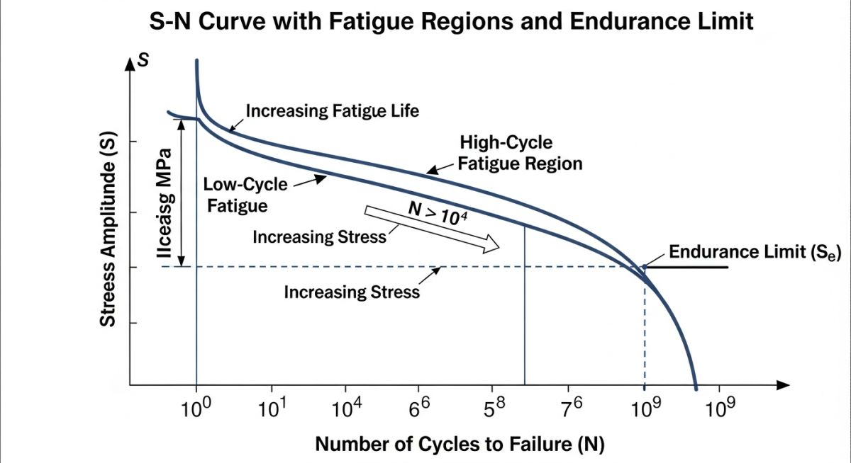
Fatigue in piping systems is generally categorized into two distinct regimes: low-cycle fatigue and high-cycle fatigue. Low-cycle fatigue is typically driven by thermal expansion and contraction during plant start-up and shut-down cycles. These cycles involve high stress levels (often exceeding the material’s yield strength) but occur relatively infrequently over the plant’s lifetime—typically fewer than 10,000 cycles. High-cycle fatigue, on the other hand, is caused by mechanical vibrations, acoustic pulsations, or rapid pressure waves (such as water hammer). These stresses are usually well below the yield strength but accumulate millions of cycles very quickly.
To evaluate these cyclic effects, we rely on the S-N curve (Stress vs. Number of Cycles), which plots the alternating stress amplitude against the number of cycles to failure. For carbon steel and low-alloy steels, the curve eventually flattens out, indicating an endurance limit below which fatigue failure is theoretically impossible. However, for non-ferrous metals like aluminum or stainless steel in corrosive environments, no such endurance limit exists; every cycle, no matter how small, contributes to the cumulative damage.
The Mathematics of Cumulative Damage: Miner’s Rule
In real-world operating plants, piping systems do not experience a single, uniform cyclic load. Instead, they are subjected to a complex spectrum of varying temperatures and pressures. To evaluate this multi-amplitude loading, we use the Palmgren-Miner linear damage hypothesis, commonly known as Miner’s Rule.
The cumulative damage factor (D) is calculated using the following equation:
Where ni is the actual number of cycles accumulated at a specific alternating stress level Si, and Ni is the allowable number of cycles to failure at that same stress level, determined from the design S-N curve. According to this criterion, fatigue failure is expected when the cumulative damage factor D reaches or exceeds 1.0. In conservative industrial designs, we often limit the allowable damage factor to 0.8 or lower to account for environmental factors and material scatter.
Code Compliance Frameworks
Different codes govern how we execute these calculations. For standard process piping, ASME B31.3 provides a simplified approach using the stress range reduction factor (f). For critical, high-pressure, or complex cyclic equipment, we must turn to the more rigorous elastic-plastic fatigue analysis methods outlined in ASME Section VIII Division 2.
Standard Fatigue Analysis Design Parameters and Limits
When designing for cyclic service, selecting the correct stress range reduction factor is paramount. The table below outlines the standard relationship between equivalent full temperature cycles and the corresponding design factors as specified in ASME B31.3.
| Equivalent Cycles (N) | Stress Range Factor (f) | Typical Application Profile | Design Action Required |
|---|---|---|---|
| Up to 7,000 | 1.00 | Standard process plants with infrequent shutdowns | Standard static analysis is sufficient |
| 7,001 to 14,000 | 0.90 | Batch reactors, daily thermal cycling operations | Evaluate high-stress branch connections |
| 14,001 to 22,000 | 0.80 | Rapid thermal swing adsorption (TSA) units | Detailed fatigue screening required |
| 22,001 to 45,000 | 0.70 | Severe cyclic utility steam headers | Incorporate flexible expansion loops |
| 45,001 to 100,000 | 0.50 | Continuous cyclic process lines | Full dynamic and finite element analysis |
Technical Mapping & Specifications Matrix
To streamline your engineering workflows, use this technical mapping matrix to identify the correct physical parameters, acronyms, and code references for your next project.
| Technical Entity | Acronym | Physical Parameter | Standard Reference |
|---|---|---|---|
| Stress Intensification Factor | SIF | Dimensionless multiplier for local stress | ASME B31.3 Appendix D |
| Alternating Stress Intensity | S_alt | Half of the total range of cyclic stress (MPa) | ASME Sec VIII Div 2 |
| Fatigue Strength Reduction Factor | FSRF | Local notch sensitivity factor | ASME Sec VIII Div 2 Part 5 |
| Welding Research Council Bulletin | WRC 107/297 | Local stress calculations at nozzle junctions | WRC Bulletins |
Field Verification Checklist for Cyclic Piping
Before any cyclic piping system is signed off for commissioning, a physical walkdown is mandatory. Theoretical models in Caesar II are only as good as the real-world installation. Use this checklist during your next site walkdown to catch potential fatigue risks before they manifest as field failures.
Pre-Commissioning Fatigue Mitigation Checklist:
-
Inspect Weld Profiles: Ensure all cyclic service welds are ground smooth to a flush profile. Avoid sharp transitions, undercut, or excessive weld reinforcement, which act as severe stress raisers.
-
Verify Support Clearances: Confirm that guide supports have the specified clearances (typically 1.5mm to 3mm) to prevent binding during thermal expansion cycles. Binding causes localized bending moments that accelerate fatigue.
-
Check Spring Hanger Presets: Verify that all variable and constant effort spring hangers are set to their design cold positions and that travel stops have been removed.
-
Assess Small-Bore Connections: Ensure all small-bore branch connections (such as vents, drains, and pressure gauges) are braced in two orthogonal directions if they are located near reciprocating machinery or high-vibration sources.
-
Examine Expansion Joint Alignment: If bellows-type expansion joints are installed, verify they are not misaligned or pre-stretched beyond the manufacturer’s allowable limits.
Field Case Study: Real-World Application
The Problem: Catastrophic Steam Header Failures
At a petrochemical facility in East Asia, a 12-inch superheated steam header (operating at 420°C and 42 bar) experienced repeated cracking at a 4-inch bypass branch connection. The plant operated on a daily cycling profile due to power grid demands. The original design had passed standard static stress checks in Caesar II, but the localized thermal expansion stress range at the branch junction was severely underestimated. The weld cracked after only 14 months of operation, forcing an unscheduled plant shutdown costing over 150,000 per day.
The Engineering Outcome: Redesign and Verification
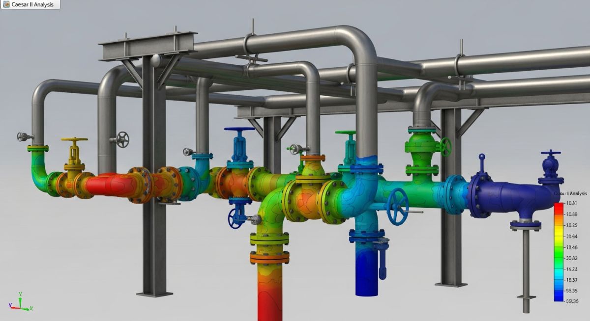
I was brought in to perform a comprehensive fatigue analysis. We remodeled the entire steam header in Caesar II, setting up a dedicated fatigue load case (FAT) that calculated the exact stress range between the hot operating condition and the cold shutdown state.
The analysis revealed that the local stress range at the branch connection was 380 MPa, far exceeding the allowable fatigue limit for 1,000 design cycles. To resolve this, we implemented two major design changes:
- Replaced the standard welded branch tee with an integrally reinforced forged branch outlet (Weldolet) to reduce the local Stress Intensification Factor (SIF) from 3.2 to 1.8.
- Added a 3D expansion loop upstream of the branch to absorb the thermal growth, reducing the overall expansion force.
The revised Caesar II model showed a drop in the alternating stress range to 145 MPa. The calculated fatigue life increased to over 25,000 cycles, ensuring safe operation for the next 25 years. The plant has now run for six years without a single incident.
My Direct Recommendation:
When modeling cyclic systems in Caesar II, always use the Fatigue Load Case option rather than relying on standard expansion (EXP) stress cases. The fatigue processor allows you to input the exact expected cycle count and directly compares the calculated stress range against the code-approved S-N curves, giving you a realistic assessment of the system’s true operating life.
Frequently Asked Engineering Questions
What is the difference between low-cycle and high-cycle fatigue?
How does ASME B31.3 handle fatigue in process piping?
Why are Stress Intensification Factors (SIFs) critical in fatigue analysis?
When should I use ASME Section VIII Division 2 for fatigue instead of B31.3?
Can Caesar II perform high-cycle fatigue analysis for acoustic vibration?
How does corrosion affect the fatigue life of piping?
===
Complete Course on
Piping Engineering
Check Now
Key Features
- 125+ Hours Content
- 500+ Recorded Lectures
- 20+ Years Exp.
- Lifetime Access
Coverage
- Codes & Standards
- Layouts & Design
- Material Eng.
- Stress Analysis